Hi guys today QIHE SMT continue sharing you with View the functions and rules of the network system High Speed PCB Design
The effect of network system in wiring
In many CAD systems, wiring is determined according to the network system.
The grid is too dense, although the passage has increased,
But the stepping is too small, the amount of data in the field is too large,
This will inevitably have higher requirements for the storage space of the equipment.
At the same time, it also has a great influence on the computing speed of computer electronic products.
And some paths are invalid,
Such as occupied by the pad of the component leg or occupied by the device hole, the fixed hole, etc.
Too sparse a grid and too few channels have a great impact on the routing rate.
Therefore, there must be a grid system with reasonable density to support the wiring.
The distance between the legs of standard components is 0.1 inches (2.54mm),
Therefore, the basis of the grid system is generally set at 0.1 inches (2.54 mm) or an integer multiple of less than 0.1 inches.
Such as: 0.05 inches, 0.025 inches, 0.02 inches, etc.
Planning Rule Review (DRC)
After wiring planning is completed,
It is necessary to carefully check whether the wiring plan conforms to the rules drawn up by the planner.
At the same time, it is also necessary to confirm whether the formulated rules meet the needs of the printed board production process,

General inspection has the following aspects:
a. Line and line, line and component pad, line and through hole, component pad and through hole,
Whether the interval between the through holes is reasonable,
Whether the production requirements are met.
b. Whether the width of the power line and the ground line is appropriate,
Is there tight coupling (low wave impedance) between power and ground?
Is there any place in the PCB where the ground wire can be widened.
c. Whether the most optimal measures have been taken for the critical signal lines,
If the length is most short, plus the maintenance line, the input line and output line are clearly separated.
d. Analog circuit and digital circuit part,
Whether there are separate ground wires.
e. Whether the graphics (such as icons and labels) added to the PCB will form a signal short circuit.
f. Modify some unsatisfactory line shapes.
g. Is there a process line on the PCB?
Whether the solder mask meets the requirements of the production process, whether the solder mask size is appropriate,
Whether the character mark is pressed on the equipment pad to avoid affecting the quality of the electrical equipment.
h. Whether the outer frame edge of the power ground layer in the multilayer board is reduced,
For example, if the copper foil of the power ground layer is exposed outside the board, it is easy to form a short circuit.
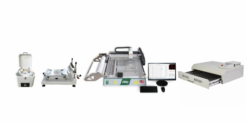
QHSMT is an enterprise specializing in the production of SMT equipment, like pick and place machine ,reflow oven,stencil printer ,smt pick and place machine,pnp,pick&place,pcb assembly,smd chip shooter,pnp machine,chip mounter,smt line,welcome to send inquiry
you can choose a reflow oven to meets your need like qfr630,qrf835,qrf1235
stencil printer model qh3040,qp3250,qfa5060
Also we have different kinds of smt pick and place machine like tvm802a,tvm802b,tvm802ax,tvm802bx,tvm802b plus,tvm925s,tvm926s,ql41,qm61,qm62,qm81,qm10
Know more about us https://www.qhsmt.com/about-qihe-smt-equipment/
Follow us on social media https://www.facebook.com/Qihesmt/
WHAT IS SMT PROCESS?
There are mainly three steps in SMT assembly line process flow: solder paste printing, components placement and reflow soldering.
- Solder Paste Printing
Its function in SMT line process is to print the solder-free paste on the pads of the PCB to prepare for the soldering of the components. The equipment used is a screen printing machine, located at the forefront of the SMT production line. - Components Placement
Its function is to accurately install the surface mount components on the fixed position of the PCB. The equipment used is a placement machine, located behind the screen printing machine in the SMT production line. - Reflow Soldering
Its function in SMT manufacturing line is to melt the solder paste so that the surface mount components and the PCB board are firmly bonded together. The equipment used is a reflow oven, located behind the placement machine in the fully automatic SMT production line.
WHAT IS SMT pick and place machine?
SMT (Surface Mounted Technology) is a comprehensive system engineering technology, which covers substrates, design, equipment, components, assembly processes, production accessories and management. When it comes to SMT pick and place machines, the automatic SMT production line requires automatic loading and unloading machine, automatic solder paste printing machine, placement machine, reflow soldering machine, AOI inspection equipment, connecting table, etc. For these SMT assembly line equipment, Qihe SMT can offer you machines in prototype SMT line, small SMT production line, mass production SMT line at low SMT line cost. Contact us now if you are interested.
WHAT IS SMT ASSEMBLY LINE?
With the development of technology, future electronic products will be lighter, smaller and thinner. Traditional assembly technology can no longer meet the requirements of high-precision and high-density assembly. A new type of PCB assembly technology-SMT (Surface Mount Technology) has emerged. SMT Assembly is the use of automated machines to assemble electronic components on the surface of the circuit board. Its density, high speed, standardization and other characteristics occupies an absolute advantage in the field of circuit assembly technology. In addition, SMT assembly has a wide range of uses.