Hi friends .Today author from QiHe smt pick and place machine sharing you with some best rules for smd components selection in PCB Design .Hope these tips could help you, please share it with more friends .
Selection of SMD component package
When selecting components, any mounting or packaging constraints that may exist on the top and bottom layers of the final PCB need to be considered.
Some components (such as polarized capacitors) may have height headroom restrictions that need to be considered during component selection. When initially starting a design, draw a basic board outline shape and then place some of the large or location-critical components that you plan to use, such as connectors.
In this way, a virtual perspective view of the circuit board (without wiring) can be seen intuitively and quickly, and relatively accurate relative positioning and component height of the circuit board and components are given. This will help ensure that the components fit properly into the outer packaging (plastic, case, frame, etc.) after the PCB is assembled. Invoke the 3D preview mode from the Tools menu to view the entire board.
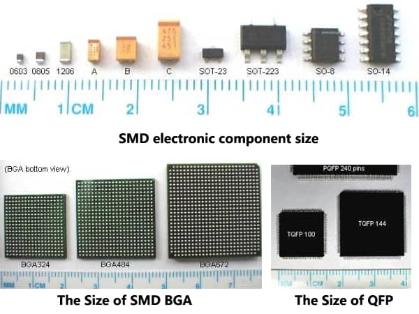
smd components types
When designing the PCB layout, you need to consider how the board will be manufactured, or how the pads will be soldered if soldered by hand. Reflow soldering (flux melting in a controlled high-temperature oven) can handle a wide variety of surface-mount devices (SMDs). Wave soldering is generally used to solder the reverse side of the circuit board to fix through-hole devices, but it can also handle some surface mount components placed on the back of the PCB.
Usually when using this technique, the bottom surface mount device must be arranged in a specific direction, and in order to accommodate this soldering method, the pad may need to be modified.
Component selection can vary throughout the design process. Determining which components should use plated through hole (PTH) and which should use surface mount technology (SMT) early in the design process will help the overall planning of the PCB. Factors to consider are device cost, availability, device area density, and power consumption, among others.
From a manufacturing standpoint, surface-mount devices are generally less expensive than through-hole devices, and generally have higher availability. For small and medium-scale prototype projects, it is best to use larger surface mount devices or through-hole devices, which not only facilitate manual soldering, but also facilitate better connection pads and signals during error checking and debugging.
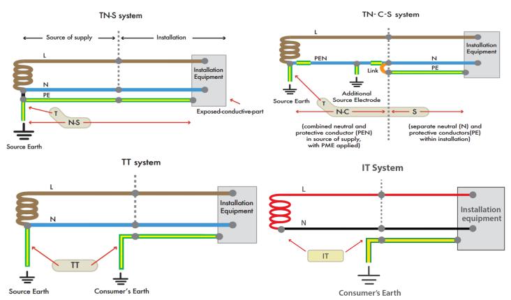
Use good grounding methods
Make sure the design has adequate bypass capacitors and ground planes. When using ICs, make sure to use proper decoupling capacitors close to the power supply terminal to ground (preferably the ground plane). The proper size of the capacitor depends on the specific application, capacitor technology, and operating frequency. When bypass capacitors are placed between the power and ground pins and placed close to the correct IC pins, the EMC and susceptibility of the circuit can be optimized.
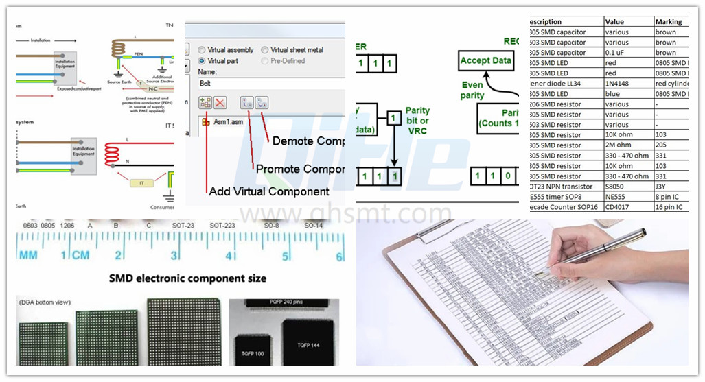
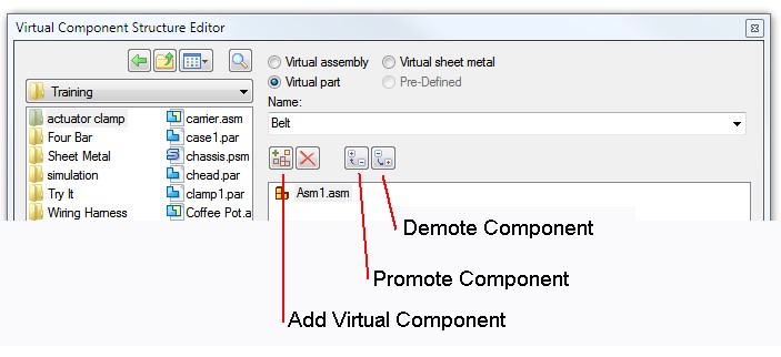
Assign virtual component packages
Print a bill of materials (BOM) for checking virtual components. Dummy components do not have an associated footprint and are not passed to the layout stage. Create a bill of materials and view all virtual components in your design.
The only entries should be power and ground signals, since they are considered virtual components and are only handled exclusively in the schematic environment and are not transferred to the layout design. Components shown in phantom should be replaced with packaged components unless used for simulation purposes.
Make sure you have complete BOM (bill of materials) data
Check that there is enough complete data in the Bill of Materials report. After creating the Bill of Materials report, perform a careful review and complete any component entries with incomplete device, supplier, or manufacturer information.

Sort according to the component number
To facilitate bill of materials sorting and viewing, ensure component designators are numbered consecutively.
Check for redundant gates
In general, the inputs of all redundant gates should have signal connections to avoid floating the input terminals. Make sure you check for any extra or missing gates, and that any unwired inputs are fully connected. In some cases, the entire system will not work properly if the input is left floating. Take the dual op amp that is often used in design.
If only one of the op amps is used in the dual op amp IC component, it is recommended to either use the other op amp, or ground the input of the unused op amp, and place an appropriate unity gain (or other gain) ) feedback network to ensure that the entire component can work properly.
In some cases, ICs with floating pins may not function properly within specifications. Usually the IC will meet the specifications only when the IC device or other gates in the same device are not operating in saturation—the input or output is close to or at the component power supply rail. Simulation often fails to capture this situation because simulation models typically do not connect parts of the IC together to model floating connection effects.
What is SMT in engineering?
Surface mount technology is a part of the electronic assembly that deals with the mounting of electronic components to the surface of a PCB. Electronic components mounted this way are called surface-mounted devices (SMD). SMT was developed to minimize manufacturing costs while making efficient use of board space.Qihe SMT company develops and produces all kinds of SMT equipment suitable for world wide market, including pnp machine,reflow oven,stencil printer,pcb handling machines,and other products.
Small desktop pick and place machine TVM802A,TVM802B,TVM802AX,TVM802BX series suitable for beginners, for hobbiest or low vol usag.
Advanced level 4-head LED strip placement QL41 led machines and with rail universal series TVM925S,TVM926S,
Fully automatic 6-10-head placement QM61,QM62,QM81,QM10,machines, which are suitable for high volume mass production in factories.
Know more about us https://www.qhsmt.com/about-qihe-smt-equipment/
Follow us on social media https://www.facebook.com/Qihesmt/
How to choose the right smt pick and place machine?
SMT Pick and place machine can execute virtually all smd material handling operations both cost-efficiently and effectively — With several designs and configurations available in the market, it can be challenging to pick one that suits your operational needs. To help you make the right decision, some factors and features you should look out for when purchasing a pick and place robot.The most important thing is the operating system, then the hardware configuration, the types of components supported, and the speed of operation, the accuracy of placement, and the smt setup cost of the entire smt line .
Qihe smt pick&place machine is a professional operating system independently developed. It has more than ten years of user experience, combined with the algorithm improvement of world-renowned colleges, and the most advanced flying camera and motion system. It is your best choice. The system is friendly for beginners and professionals.
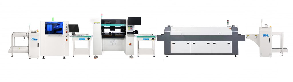
WHAT IS SMT ASSEMBLY LINE?
With the development of technology, future electronic products will be lighter, smaller and thinner. Traditional assembly technology can no longer meet the requirements of high-precision and high-density assembly. A new type of PCB assembly technology-SMT (Surface Mount Technology) has emerged. SMT Assembly is the use of automated machines to assemble electronic components on the surface of the circuit board. Its density, high speed, standardization and other characteristics occupies an absolute advantage in the field of circuit assembly technology. In addition, SMT assembly has a wide range of uses.