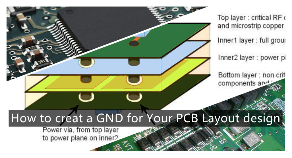
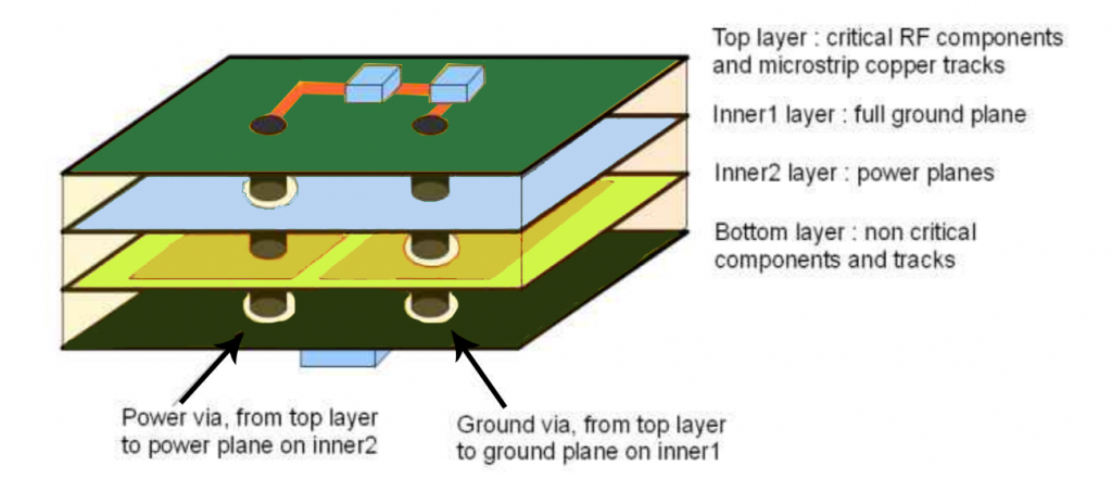
How to creat a GND for Your PCB Layout design? The power earthing is mainly for the path of the power loop current. Generally speaking, the current flowing through the power ground is relatively large, and the signal grounding is mainly for the backflow of the communication signal between two chips or modules. Path, generally speaking, the current flowing through the signal ground is very small. In fact, both are GND. The reason why they are separated is to let everyone understand that when laying out the PCB board, it is necessary to clearly understand the flow of the power supply and the signal return flow. path, and then consider how to avoid the common return path of power supply and signal when laying out the board. If it is shared, it may cause a large current on the power supply ground to generate a voltage difference on the signal ground (it can be interpreted as: the wire has impedance, but A small resistance value, but if the current flowing through is large, a potential difference will also be generated on this wire, which is also called common impedance interference), so that the real potential of the signal ground is higher than 0V, if the potential of the signal ground When it is larger, it may cause the signal to be high level, but it is misjudged as low level.
Of course, the ground of the power supply is inherently complex, and doing so also avoids signal misjudgment due to interference. So just pay attention to the two grounds when wiring. Generally speaking, even together, there will be no major problems, because the threshold of digital circuits is relatively high.
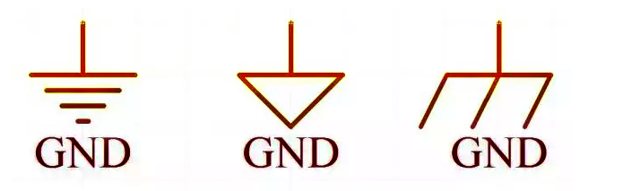
GND refers to the abbreviation of the ground terminal of the wire. Represents ground or 0 wire.
GND (Ground) on the circuit diagram and on the circuit board represents the ground or 0 line. GND means the common terminal, and it can also be said to be the ground, but this ground is not the real ground. It is a ground assumed for the application, and for the power supply, it is the negative pole of a power supply. It is different from the earth. Sometimes it needs to be connected to earth, sometimes it doesn’t, it depends.
Explanation of various groundings
The signal ground of the device may be a point or a piece of metal in the device as the ground reference point of the signal, which provides a common reference potential for all signals in the device.
There are single-point grounding, multi-point grounding, floating grounding and mixed grounding.
Single-point grounding means that only one physical point in the entire circuit system is defined as a ground reference point, and all other points that need to be grounded are directly connected to this point. In low frequency circuits, there is not much influence between wiring and components. Generally, for circuits with a frequency less than 1MHz, one point is used for grounding.
Multi-point grounding means that each grounding point in electronic equipment is directly connected to the ground plane closest to it (that is, the metal bottom plate of the equipment). In high-frequency circuits, parasitic capacitance and inductance have a greater influence. Generally, circuits with a frequency greater than 10MHz often use multi-point grounding.
Floating ground, that is, the ground of the circuit is not connected to the earth by a conductor. Virtual ground: A point that is not grounded but is at the same potential as ground.
The advantage is that the circuit is not affected by the earth’s electrical properties. The floating ground can make the isolation resistance between the power ground (strong electric ground) and the signal ground (weak electric ground) very large, so it can prevent the electromagnetic interference generated by the common ground impedance circuit coupling.
Its disadvantage is that the circuit is easily affected by parasitic capacitance, which changes the ground potential of the circuit and increases the inductive interference to the analog circuit.
“Grounding” includes the signal grounding inside the device and the grounding of the device. The concepts and purposes of the two are different. The classic definition of “ground” is “an equipotential point or plane that serves as a reference for a circuit or system.”
The signal “ground” is also called the reference “ground”, which is the reference point of zero potential and also the common terminal that constitutes the circuit signal loop.
(1) DC ground: DC circuit “ground”, zero potential reference point.
(2) AC ground: the neutral line of AC. It should be distinguished from the ground wire.
(3) Power ground: the zero-potential reference point of high-current network devices and power amplifier devices.
(4) Analog ground: the zero-potential reference point of amplifiers, sample-and-hold devices, A/D converters, and comparators.
(5) Digital ground: Also called logic ground, it is the zero potential reference point of digital circuits.
(6) “Hot ground”: Switching power supply does not need to use a power frequency transformer, and the “ground” of its switching circuit is related to the mains power grid, that is, the so-called “hot ground”, which is charged.
(7) “Cold ground”: Because the high-frequency transformer of the switching power supply isolates the input and output terminals; and because the feedback circuit commonly used optocoupler, it can not only transmit the feedback signal, but also isolate the “ground” of both sides; so the output terminal The ground is called “cold ground”, it is not charged.
signal grounding
The signal ground of the device may be a point or a piece of metal in the device as the ground reference point of the signal, which provides a common reference potential for all signals in the device.
There are single-point grounding, multi-point grounding, floating grounding and mixed grounding. (Floating ground is mainly introduced here) Single-point grounding means that only one physical point in the entire circuit system is defined as the ground reference point, and all other points that need to be grounded are directly connected to this point. In low frequency circuits, there is not much influence between wiring and components. Generally, for circuits with a frequency less than 1MHz, one point is used for grounding. Multi-point grounding means that each grounding point in electronic equipment is directly connected to the ground plane closest to it (that is, the metal bottom plate of the equipment). In high-frequency circuits, parasitic capacitance and inductance have a greater influence. Circuits with a frequency greater than 10MHz are often used
Multiple grounding
Floating ground, that is, the ground of the circuit is not connected to the earth by a conductor. 『 False ground: A point that is not grounded but is at the same potential as ground. 』The advantage is that the circuit is not affected by the performance of the earth. The floating ground can make the isolation resistance between the power ground (strong electric ground) and the signal ground (weak electric ground) very large, so it can prevent the electromagnetic interference generated by the common ground impedance circuit coupling. Its disadvantage is that the circuit is easily affected by parasitic capacitance, which changes the ground potential of the circuit and increases the inductive interference to the analog circuit. A compromise is to connect a large bleeder resistor across the floating ground to the common ground to discharge the accumulated charge. Pay attention to controlling the impedance of the release resistor, too low resistance will affect the qualification of the leakage current of the equipment.
Equipments grounding
In engineering construction, in addition to carefully considering the signal grounding inside the equipment, the signal ground of the equipment, the chassis and the ground are usually connected together, and the ground is used as the grounding reference point of the equipment. The purpose of grounding the device is to
1) Protective ground, protective grounding is to make a good electrical connection between the metal shell (or frame) and the grounding device when the equipment is in normal operation. A wiring method set up to protect the safety of personnel. One end of the protective “ground” wire is connected to the electrical shell, and the other end is reliably connected to the earth.
2) Anti-static grounding, discharge the accumulated charge on the chassis, and avoid the potential increase of the chassis caused by the accumulation of charge, resulting in unstable circuit operation.
3) Shield the ground to prevent the equipment from changing the potential of the equipment to the ground under the action of the external electromagnetic environment, resulting in unstable operation of the equipment.
In addition, there are lightning protection grounding and audio dedicated ground in the audio system, etc.
About QIHE SMT pick and place machine
QiHe Electrical Technology Co.,LTD is a high-tech company,which located in Economic Development Zone, Yueqing,China. We professional designing and producing all kinds of , pick and place machine,reflow oven,stencil printer, We also providing SMT solutions .Our Products playing a leading role in SMT industry. We have set a long lasting cooperation and partnership with global customers .Warmly welcome you to visit our company for friendship and cooperation.
Know more about us https://www.qhsmt.com/about-qihe-smt-equipment/
Follow us on social media https://www.facebook.com/Qihesmt/
What is SMT in engineering?
Surface mount technology is a part of the electronic assembly that deals with the mounting of electronic components to the surface of a PCB. Electronic components mounted this way are called surface-mounted devices (SMD). SMT was developed to minimize manufacturing costs while making efficient use of board space.Qihe SMT company develops and produces all kinds of SMT equipment suitable for world wide market, including pnp machine,reflow oven,stencil printer,pcb handling machines,and other products.
Small desktop pick and place machine TVM802A,TVM802B,TVM802AX,TVM802BX series suitable for beginners, for hobbiest or low vol usag.
Advanced level 4-head LED strip placement QL41 led machines and with rail universal series TVM925S,TVM926S,
Fully automatic 6-10-head placement QM61,QM62,QM81,QM10,machines, which are suitable for high volume mass production in factories.
WHAT IS SMT pick and place machine?
SMT (Surface Mounted Technology) is a comprehensive system engineering technology, which covers substrates, design, equipment, components, assembly processes, production accessories and management. When it comes to SMT pick and place machines, the automatic SMT production line requires automatic loading and unloading machine, automatic solder paste printing machine, placement machine, reflow soldering machine, AOI inspection equipment, conveyor,connecting table, etc. For these SMT assembly line equipment, Qihe SMT can offer you machines in prototype SMT line, small SMT production line, mass production SMT line at low SMT line cost. Contact us now if you are interested.
WHAT IS SMT ASSEMBLY LINE?
With the development of technology, future electronic products will be lighter, smaller and thinner. Traditional assembly technology can no longer meet the requirements of high-precision and high-density assembly. A new type of PCB assembly technology-SMT (Surface Mount Technology) has emerged. SMT Assembly is the use of automated machines to assemble electronic components on the surface of the circuit board. Its density, high speed, standardization and other characteristics occupies an absolute advantage in the field of circuit assembly technology. In addition, SMT assembly has a wide range of uses.
SMT line for pcb layout design