How is smt pick and place machine stencil made ?
At present, there are four main types of stencils commonly used in the SMT process according to the manufacturing method: chemically etched stencils; laser-cut stencils; electroformed stencils and mixed-process stencils. qhsmt technology will briefly introduce the production methods of these four stencils before you use smt pick and place machine.
Chemical etching steel mesh qihe smt pick and place machine
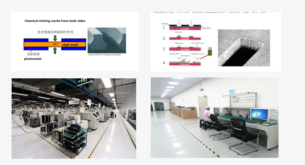
Chemical etching is to use a corrosive chemical solution to eliminate the metal corrosion of the stainless steel sheet where the holes need to be opened, and obtain the openings corresponding to the PCB pads to meet the steel mesh required for SMT chip processing and production. Its manufacturing process is as follows:
Cut a steel sheet of suitable size → clean → apply photoresist material → UV exposure → development, drying → chemical etching → stripping photoresist material → cleaning, drying → inspection → stretching net → packaging
Since chemical etching removes metal parts from both sides of the steel sheet at the same time (as shown on the left below), the hole wall is smooth and vertical, but the metal may not be completely removed in the central part of the thickness of the steel sheet to form a conical shape with a water-like cross section. The shape of the drain (as shown on the right below), this structure is not conducive to the release of solder paste.
Therefore, etched stencils are generally not recommended for precision component assembly. Usually the pitch of the component is less than 0.5mm, or the etched steel mesh is not recommended for components below 0402 size. Of course, for the assembly of some large components or components with a large pitch value, the etched steel mesh has a greater cost advantage, and can also meet the production quality requirements of many Guangzhou SMT chip processing plants.
Laser cutting steel mesh qihe smt pick and place machine
The high-energy laser beam is used to cut and punch holes on the stainless steel sheet to obtain the required steel mesh technology. Its manufacturing process is as follows:
Data processing→laser drilling→grinding, electropolishing→inspection→stretching mesh→packaging
The principle of laser cutting is shown in the left figure below. The cutting process is finely controlled by the machine and is suitable for the production of ultra-small spacing openings.
Because it is directly ablated by laser, the hole wall is straighter than the chemically etched hole wall, and there is no intermediate tapered shape, which is conducive to filling the mesh with solder paste. And because it is ablated from one side to the other
The hole wall will present a natural inclination angle, making the cross-section of the entire hole an inverted trapezoid structure (as shown in the right figure below), and this taper is roughly equivalent to half the thickness of the steel sheet.
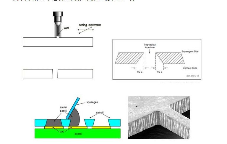
The inverted trapezoidal structure is beneficial for solder paste release, and a better “brick” or “coin” shape can be obtained for small-hole pads, which is suitable for fine-pitch or micro-component assembly. Therefore, laser stencils are generally recommended for SMT assembly of precision components.
Electroforming steel mesh qihe smt pick and place machine
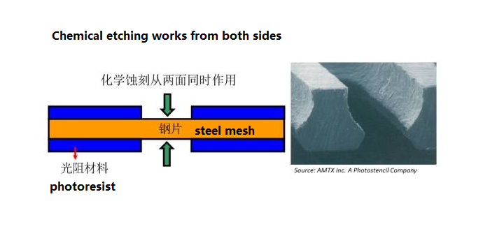
The most complex steel mesh manufacturing technology uses the electroplating addition process to generate nickel sheets of required thickness around the pre-finished mandrel. The size is accurate and does not require post-processing to compensate for the hole size and hole wall surface. Its manufacturing process is as follows:
Coating photosensitive film on substrate → making mandrel → electroplating nickel to generate steel sheet around the mandrel → peeling and cleaning → inspection → stretching net → packaging
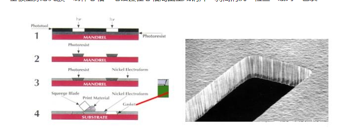
Electroformed steel mesh with smooth wall, inverted trapezoidal structure, best solder paste release, good printing performance for micro BGA, ultra-fine pitch QFP and small chip components such as 0201, 01005.
And due to the characteristics of the electroforming process itself, a ring-shaped protrusion slightly higher than the thickness of the steel sheet is formed on the edge of the hole, which is quite a “sealing ring” during solder paste printing.
The solder mask adheres tightly to prevent the leakage of solder paste to the outside of the pad. Of course, the steel mesh cost of this process is also the highest.
Mixed process steel mesh qihe smt pick and place machine
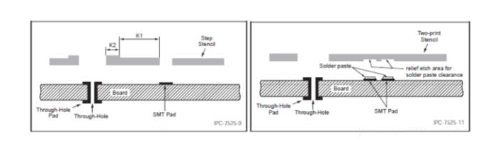
The hybrid process is actually the so-called stepped steel mesh production technology. The stepped steel mesh is to retain more than two thicknesses on a steel mesh.Which is different from the steel mesh that we generally use with only one thickness.
The purpose of its production is mainly to meet the different requirements of different components on the board for the amount of tin.
The step stencil manufacturing process is to combine one or two of the previous three stencil processing processes to jointly produce a stencil.
Generally speaking, many Guangzhou SMT chip processing plants will first use chemical etching methods to obtain our The required thickness of the steel sheet is then laser cut to complete the hole processing.
There are two types of stepped steel mesh, Step-up and Step-down.
The production process of the two types is basically the same, and whether it is Up or Down depends on whether the part that needs to be changed is to increase or decrease the thickness.
In order to meet the assembly requirements of local small-pitch components on a large board (such as CSP on a large board), most components on the board need more tin, while for small-pitch CSP or QFP components
In order to prevent short circuits, it needs to be reduced The amount of tin, or the need for air avoidance treatment, can use Step-down steel mesh to thin the steel sheet at the position of small-pitch components.
So that the thickness of the steel sheet here is smaller than the thickness of other positions. In the same way, for a small number of large-lead components on some precision boards.
Due to the thin overall thickness of the steel sheet, the amount of solder paste deposited on the pad may be insufficient, or for the through-hole reflow process
It is sometimes necessary to fill the through-hole with a larger amount. The amount of solder paste is required to meet the solder filling requirements in the hole.
Which requires increasing the thickness of the steel sheet at the large pad or through-hole position of the stencil to increase the amount of solder paste deposition,
Which requires the use of Step-up stencils. In actual production, we need to determine which steel mesh to choose according to the type and distribution of components on the board.
you can choose a reflow oven to meets your need like qfr630,qrf835,qrf1235
stencil printer model qh3040,qp3250,qfa5060
Also we have different kinds of smt pick and place machine like tvm802a,tvm802b,tvm802ax,tvm802bx,tvm925s,tvm926s,ql41,qm61,qm62,qm81,qm10
Qihe smt pick and place machine catalog
-
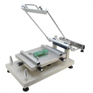
 Benchtop Manual Smt Frameless PCB Solder Paste Stencil Printer Printing Machine
 -
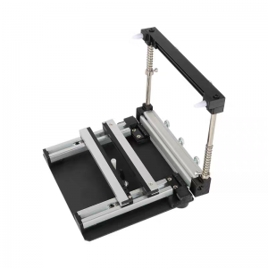
SMT Manual Frameless Pcb Solder Paste Stencil Printer
-
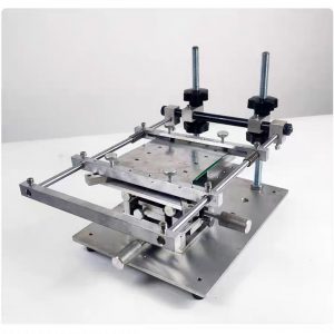
SMT frameless steel stencil screen printing table
-
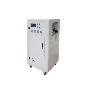
Nitrogen generator, used for selective welding
-
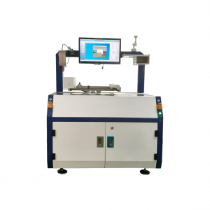
Desktop selection welding QSO-300B
-
Desktop Selective Wave Soldering Machine QH-SHSS341
-
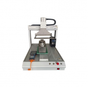
SMT semi-automatic pick and place machine with Dispenser
-
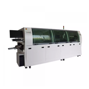
QiHe series wave soldering machine
-
High-speed off-line selective wave soldering QSO-300

FAQ about smt pick and place machine
WHAT IS SMT pick and place machine?
SMT (Surface Mounted Technology) is a comprehensive system engineering technology, which covers substrates, design, equipment, components, assembly processes, production accessories and management. When it comes to SMT pick and place machines, the automatic SMT production line requires automatic loading and unloading machine, automatic solder paste printing machine, placement machine, reflow soldering machine, AOI inspection equipment, connecting table, etc. For these SMT assembly line equipment, Qihe SMT can offer you machines in prototype SMT line, small SMT production line, mass production SMT line at low SMT line cost. Contact us now if you are interested.
WHAT IS SMT ASSEMBLY LINE?
With the development of technology, future electronic products will be lighter, smaller and thinner. Traditional assembly technology can no longer meet the requirements of high-precision and high-density assembly. A new type of PCB assembly technology-SMT (Surface Mount Technology) has emerged. SMT Assembly is the use of automated machines to assemble electronic components on the surface of the circuit board. Its density, high speed, standardization and other characteristics occupies an absolute advantage in the field of circuit assembly technology. In addition, SMT assembly has a wide range of uses.
WHAT IS SMT PROCESS?
There are mainly three steps in SMT assembly line process flow: solder paste printing, components placement and reflow soldering.
- Solder Paste Printing
Its function in SMT line process is to print the solder-free paste on the pads of the PCB to prepare for the soldering of the components. The equipment used is a screen printing machine, located at the forefront of the SMT production line.
- Components Placement
Its function is to accurately install the surface mount components on the fixed position of the PCB. The equipment used is a placement machine, located behind the screen printing machine in the SMT production line.
- Reflow Soldering
Its function in SMT manufacturing line is to melt the solder paste so that the surface mount components and the PCB board are firmly bonded together. The equipment used is a reflow oven, located behind the placement machine in the fully automatic SMT production line.
by the way regarding the TVM802BX machine,There is one note: The camera cannot be positioned at left 1 slot, the left 1 can only be positioned with the suction nozzle ,not use camera model ,Otherwise, it may cause the impact of the placement head.