Many friends who are first time to research SMT equipment often have such question:
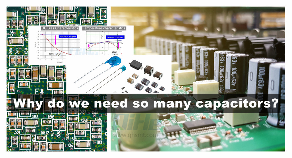
Why do PCB assembly have so many capacitors?
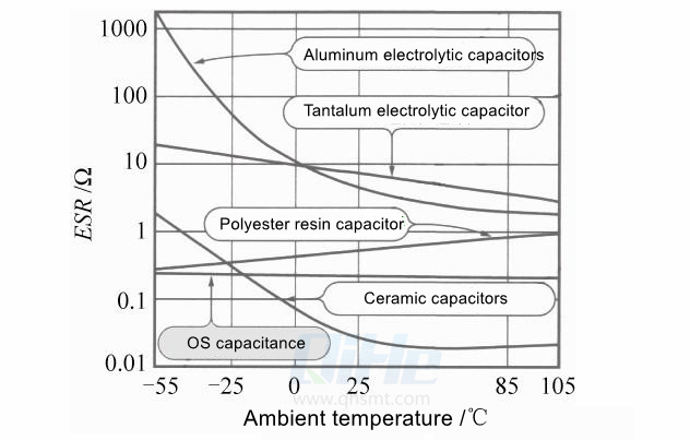
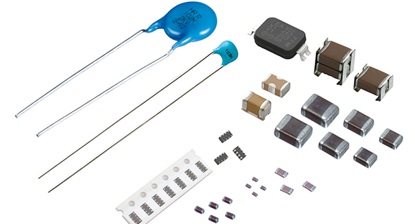
today we share some knowledge about capacitors electronic components.You may know many types of capacitors, such as Aluminum electrolytic capacitors, Tantalum electrolytic capacitors, Polyester resin capacitors, Ceramic capacitors, OS capacitance. Through today’s sharing, I hope it can help you before setup smt line for pcba phototype.We all know that capacitors are the most used components in circuits. The capacitors we often come into contact with are ceramic capacitors, aluminum electrolytic capacitors, and tantalum electrolytic capacitors. More and more of our circuit designs are digital circuit designs with MCU and CPU as the core, and peripheral clock and power circuits. So we mainly use these three types of capacitors.
Because of the digital circuit, there are a large number of “0” and “1” flips output by the digital circuit, which requires a large number of decoupling capacitors.
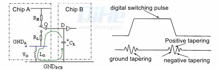
Different positions of the switch Q in the figure represent two states of the output “0” and “1”.
Assume that due to the change of the circuit state, the switch Q is connected to the RL low level, and the load capacitor discharges to the ground. As the load capacitor voltage drops, the accumulated charge flows to the ground, forming a large current surge on the ground loop.
As the discharge current builds up and then decays, this current change acts on the inductance LG of the ground pin, so that a certain voltage difference will be formed between the “ground” of the circuit board outside the chip and the ground inside the chip, as shown in the figure VG . Similarly, for the power supply terminal, every time the signal is flipped, a voltage difference will be introduced.
When more than N flips occur, we need to use decoupling capacitors, which can prevent this noise from spreading outward, so we put some capacitors close to the power supply pins of the device.
Since the decoupling capacitor generally does not have strict requirements on the accuracy of the capacitor, it can be selected according to the design value, and a capacitor with a similar capacity or a capacity close to it can be selected.
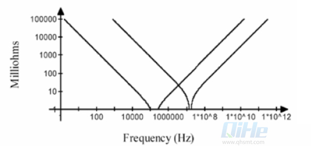
Actual capacitors have parasitic inductance and equivalent series resistance. Since the ESR and ESL of a single capacitor are similar, their impedance characteristics are also similar.
The impedance characteristic diagram of a single capacitor and multiple capacitors with the same characteristics in parallel.
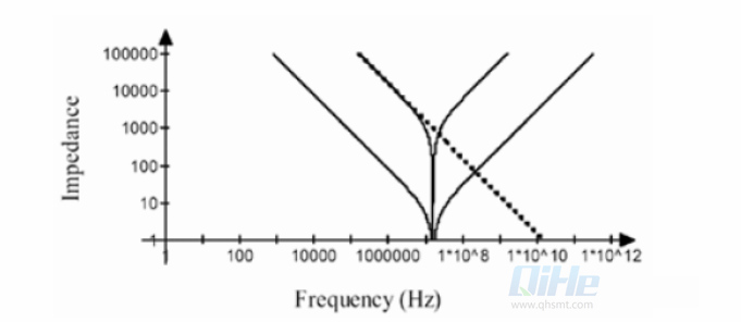
Capacitors with different values
So in this scenario, we need a kind of:
- 1nF~10uF capacity, the accuracy requirement is not high;
- Due to the relatively large amount (more power supply pins), the cost is relatively low, and the volume is relatively small under the same capacity;
- Capacitors with relatively small ESR and ESL. (The signal frequency that needs to be decoupled is relatively high, and the decoupling effect is guaranteed)
Multilayer ceramic capacitors (MLCCs) are very suitable.
One principle of the decoupling design of the power system is to minimize the impedance of the entire power distribution system within the frequency range to be considered.
Since chips, especially CPU, FPGA, DSP, etc., multi-IO and high-power chips are the core of the circuit, these chips also have more power pins, so the amount of decoupling capacitors is relatively large.
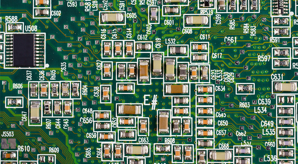
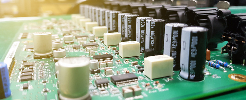
Capacitors in PCB assembly
Generally, as the rate of our chips is getting higher and higher, the interface level is getting lower and lower, resulting in power supplies with various voltage values on our circuit boards. The early digital circuit power supplies were mainly 5V and 3.3V. The circuit power supply is more abundant: 2.5V, 1.8V, 1.5V, 1.1V, 1.0V, 0.9V, adjustable and controllable power supply and so on. Therefore, the input and output capacitors of these switching power supplies also need to be used in large quantities.
Since the capacity of aluminum electrolytic capacitors is easy to increase and the withstand voltage is relatively high, aluminum electrolytic capacitors are mainly selected as the input capacitors of the power supply. The output capacitor will choose aluminum electrolytic capacitor and tantalum capacitor. Capacitance of aluminum electrolytic capacitor: 0.47–10000u, rated voltage: 6.3–450V. The main features of aluminum electrolytic capacitors: small size, large capacity, large loss, large leakage, and relatively high withstand voltage.
In the early days, aluminum electrolytic capacitors were used for the input and output capacitors of switching power supplies. In scenarios where the expected ESR is relatively small, we will choose tantalum electrolytic capacitors.
However, aluminum electrolytic capacitors have a fatal weakness, that is, the electrolyte will dry up, the life is relatively short, and the ESR is relatively large. Tantalum electrolytic capacitors will explode due to their horrible failure modes, which may cause combustion.
At present, with the continuous development of MLCC technology, we will use MLCC instead of aluminum electrolytic capacitors at the input and output ends of some low-current and low-voltage switching power supplies.
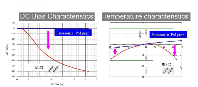
Generally speaking, the output capacitance of the switching power supply is generally above 100uF. Although the nominal value of the ceramic capacitor can reach 100uF, due to its poor temperature stability, the capacitance value will increase with the increase of the DC voltage. The main reason is that the capacitance of the output capacitor may need hundreds or even thousands of uF. If ceramic capacitors are used, the filtering effect will not be achieved due to the limited capacity of the individual capacitors.
At present, a large number of solid tantalum capacitors and solid aluminum capacitors are gradually replacing aluminum electrolytic capacitors and tantalum electrolytic capacitors.
Compared with aluminum electrolytic capacitors, it has a longer life and is more reliable; compared with MnO2 tantalum electrolytic capacitors, there is no terrible failure mode, and it is less likely to fail. Compared with MLCC, the DC bias characteristic is more stable and the temperature characteristic is more stable.
The biggest problem is: expensive. At present, some industries with relatively high profits have gradually used solid aluminum electrolytic capacitors in large quantities. Due to the relative scarcity of tantalum element, there is a possibility of global depletion. So solid aluminum capacitors are being used more and more.
Since the withstand voltage and capacity need to be further improved, there is still a development process. However, capacitors, like CPUs, will follow a law similar to Moore’s Law and develop rapidly.
But solid capacitors also have weaknesses. The actual use of fixed capacitors is polymer (Polymer). Polymer tantalum capacitors are slightly less thermally stable than MnO2 tantalum capacitors. MnO2 tantalum capacitors do not have the problem of aging life, while the degradation mechanism of Polymer capacitors is mainly due to the decomposition of polymer organisms at high temperatures, resulting in a decrease in conductivity, which can be considered semi-permanent failure. Polymer tantalum capacitors are not as good as MnO2 tantalum capacitors in terms of moisture sensitivity. The main reason is that the cathode material Polymer will react with water and oxygen and decompose at a certain temperature, resulting in a decrease in capacity, ESR and other characteristics or even failure. Therefore, it is particularly required that under the conditions of reflow soldering temperature, there should be no moisture intrusion.
The essence of the above is power filtering.
There are actually no particularly strict requirements for temperature stability and accuracy. So it is also the most commonly used capacitors.
MLCCs are not just for decoupling capacitors or power supply filtering. Oscillators, resonator tank capacitors, and coupling capacitors in high-frequency circuits. At this time, ordinary X7R and X5R ceramic capacitors with ordinary characteristics can no longer meet the requirements. We need ceramic capacitors with better temperature characteristics.
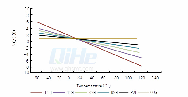
C0G capacitors with temperature compensation are suitable for oscillators, tank capacitors for resonators, and coupling capacitors in high-frequency circuits.
However, in addition to scenarios such as power filtering, energy storage, and decoupling, analog circuits also have a more important application that is signal filtering. The essence of AC coupling is a kind of signal filtering.
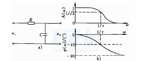
When RC and LC filter, the accuracy and stability of C value is particularly important. From the above figure, we can know that the capacitance of the capacitor will affect the amplitude-frequency characteristics and phase-frequency characteristics.
In some multi-channel signal scenarios, it is necessary to ensure the signal phase consistency and stability of each channel, such as phased array radar, sonar system, etc., we need to accurately control the capacitance of the capacitor.
In the clock or radio frequency signal, we also need oscillators, resonators, etc., not only need stable and accurate capacitance value, but also need better Q value.
At this time, non-polar tantalum capacitors, polystyrene capacitors, high-stability ceramic capacitors, and mica capacitors have their own unique demand scenarios.
When we design a primary power supply (ACDC), we also need to use safety capacitors. The requirements are: small internal resistance and high withstand voltage. Safety capacitor is the industry’s common name for fixed capacitors used to suppress power supply electromagnetic interference. Because this type of capacitor complies with safety regulations and has passed safety standard testing and certification, and its body is printed with safety certification LOGO marks from multiple countries, it is called safety regulation capacitor. The “safety regulations” of this type of capacitor in practical applications are as follows: even if the capacitor fails, it will not cause electric shock and will not endanger personal safety; in addition, it is made of flame-retardant materials, and it will explode at most (just burst, no fire) produce, only produce gas), and then it is an open circuit, which will not cause a fire. Polyester film capacitors meet the needs of this scenario.
Usually, X capacitors use polyester film capacitors with relatively large ripple currents. This type of capacitor has a large volume, but it allows a large current for instantaneous charging and discharging, and its internal resistance is correspondingly small. Ordinary capacitors have very low ripple current indicators and high dynamic internal resistance. Replacing the X capacitor with an ordinary capacitor, in addition to the capacitor withstand voltage cannot meet the standard, the ripple current index is also difficult to meet the requirements.
In the process of circuit design, due to different application scenarios, we need different parameters such as capacitance value, withstand voltage, accuracy, temperature stability, voltage stability, Q value, ESR, ESL and so on. However, the capacitance of a process and material is difficult to meet various scenarios of circuit design. Therefore, various capacitors are continuously derived. It’s just that digital circuits are developing rapidly, while analog circuits are relatively gradually shrinking, so many types of capacitors are no longer known to hardware engineers.
Read more: Why do PCB assembly have so many capacitors?About QIHE SMT pick and place machine
QiHe Electrical Technology Co.,LTD is a high-tech company,which located in Economic Development Zone, Yueqing,China. We professional designing and producing all kinds of , pick and place machine,reflow oven,stencil printer, We also providing SMT solutions .Our Products playing a leading role in SMT industry. We have set a long lasting cooperation and partnership with global customers .Warmly welcome you to visit our company for friendship and cooperation.
Know more about us https://www.qhsmt.com/about-qihe-smt-equipment/
Follow us on social media https://www.facebook.com/Qihesmt/
WHAT IS SMT pick and place machine?
SMT (Surface Mounted Technology) is a comprehensive system engineering technology, which covers substrates, design, equipment, components, assembly processes, production accessories and management. When it comes to SMT pick and place machines, the automatic SMT production line requires automatic loading and unloading machine, automatic solder paste printing machine, placement machine, reflow soldering machine, AOI inspection equipment, conveyor,connecting table, etc. For these SMT assembly line equipment, Qihe SMT can offer you machines in prototype SMT line, small SMT production line, mass production SMT line at low SMT line cost. Contact us now if you are interested.
WHAT IS SMT ASSEMBLY LINE?
With the development of technology, future electronic products will be lighter, smaller and thinner. Traditional assembly technology can no longer meet the requirements of high-precision and high-density assembly. A new type of PCB assembly technology-SMT (Surface Mount Technology) has emerged. SMT Assembly is the use of automated machines to assemble electronic components on the surface of the circuit board. Its density, high speed, standardization and other characteristics occupies an absolute advantage in the field of circuit assembly technology. In addition, SMT assembly has a wide range of uses.
Best seller SMT Machine :Qihe smt line products
-
 SMT semi-automatic pick and place machine with Dispenser
 -
TVM925 SMT pick and place machine 4 head 38 feeders slots assembly of electronic components
-
Q10 SMT Automatic pick and place machine 10 Heads 100 Slots High Precision and High Efficiency SMT/LED Assembly
-
Q6 SMT pick and place machine 6heads 50slots With PCB Rail Servo Pick&Place Machine
-
Q4 SMT pick and place machine 4heads 50slots With PCB Rail Servo Pick&Place Machine
-
TVM802B Plus SMT pick and place machine 2heads 58slots desktop pick&place deluxe edition
-
QM10 SMT pick and place machine 10heads 80slots Fully Automatic Chip mounter SMT Assembly
-
TVM802BX SMT pick and place machine 2heads 46slots desktop pnp mounter deluxe edition
-
QL41 SMT pick and place machine 4heads 8slots LED for 1.2meters led strip pick&place machine


QM81 smd pcb assembly