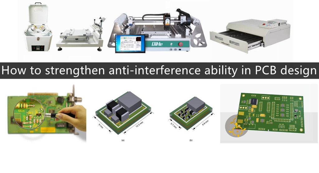
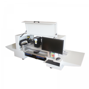
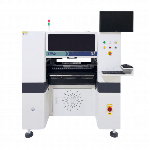
Printed circuit boards (PCBs) are the supporting components for circuit components and devices in electronic products in smt assembly. It provides electrical connections between circuit components and devices. With the rapid development of electronic technology, the density of PCBs is getting higher and higher. The quality of PCB design has a significant impact on its anti-interference ability. Practice has proven that even if the circuit schematic design is correct and the printed circuit board design is inappropriate, it can have adverse effects on the reliability of electronic products. For example, if two thin parallel lines of a printed circuit board are placed very close together, it will cause a delay in the signal waveform and generate reflected noise at the terminals of the transmission line. Therefore, when designing printed circuit boards, attention should be paid to adopting the correct methods, following the general principles of PCB design, and meeting the requirements of anti-interference design
To achieve optimal performance in electronic circuits, the layout of components and the placement of wires are crucial. In order to design high-quality and low-cost PCBs,
the following general principles should be followed:
Firstly, consider the size of the PCB. When the PCB size is too large, the printed lines are long, the impedance increases, the noise resistance decreases, and the cost also increases; If it is too small, the heat dissipation is poor, and adjacent lines are easily disturbed. After determining the PCB size, determine the position of special components. Finally, layout all components of the circuit according to its functional units.
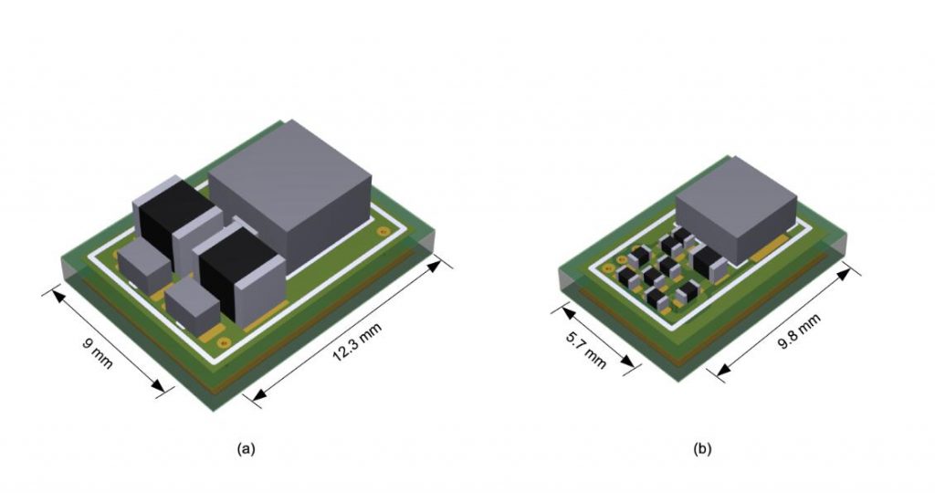
When determining the position of special components, the following principles should be followed:
Try to shorten the wiring between high-frequency components as much as possible, and try to reduce their distribution parameters and electromagnetic interference with each other. Components that are susceptible to interference should not be too close to each other, and input and output components should be kept as far away as possible.
There may be a high potential difference between certain components or wires, and the distance between them should be increased to avoid accidental short circuits caused by discharge. Components with high voltage should be arranged in areas that are not easily accessible by hands during debugging.
Components weighing over 15g should be fixed with brackets and then welded. The components that are large, heavy, and generate a lot of heat should not be installed on the printed circuit board, but on the chassis bottom plate of the entire machine, and heat dissipation should be considered. The thermal element should be kept away from the heating element.
For the layout of adjustable components such as Potentiometer, adjustable inductance coil, variable capacitor, microswitch, etc., the structural requirements of the whole machine shall be considered. If it is adjusted internally, it should be placed in a convenient place on the printed circuit board for adjustment; If it is adjusted externally, its position should match the position of the adjustment knob on the chassis panel.
The position occupied by the positioning holes and fixing brackets of the printed board should be reserved.
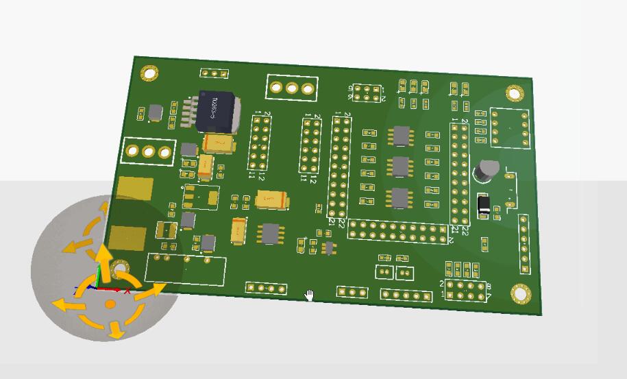
According to the functional units of the circuit. When PCB layout is applied to all components of a circuit, the following principles should be followed:
Arrange the positions of each functional circuit unit according to the circuit flow, making the layout convenient for signal flow and keeping the signal in the same direction as much as possible.
Layout around the core components of each functional circuit as the center. The components should be evenly, neatly, and compactly arranged on the PCB. Minimize and shorten the leads and connections between various components as much as possible.
For circuits operating at high frequencies, consideration should be given to the distribution parameters between components. The general circuit should arrange the components in parallel as much as possible. In this way, not only is it aesthetically pleasing, but it is also easy to assemble and weld, making it easy for mass production.
The components located at the edge of the circuit board are generally not less than 2mm away from the edge of the circuit board. The optimal shape of a circuit board is a rectangle. Both length and width are 3:2 or 4:3. Circuit board size greater than 200 × At 150mm, the mechanical strength of the circuit board should be considered.
Best seller SMT Machine :Qihe smt line products
-
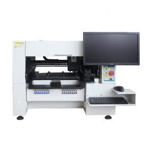
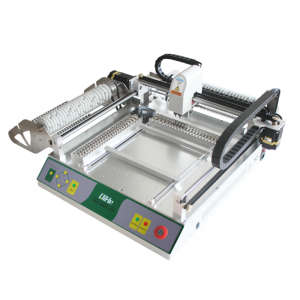
TVM925 SMT pick and place machine 4 head 38 feeders slots assembly of electronic components
-
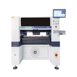
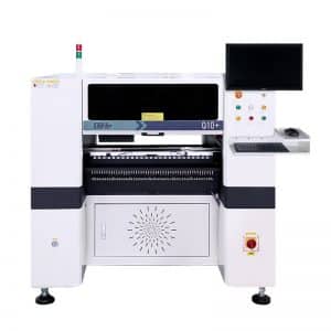
Q10 SMT Automatic pick and place machine 10 Heads 100 Slots High Precision and High Efficiency SMT/LED Assembly
-
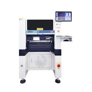
Q6 SMT pick and place machine 6heads 50slots With PCB Rail Servo Pick&Place Machine
-
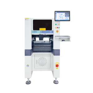
Q4 SMT pick and place machine 4heads 50slots With PCB Rail Servo Pick&Place Machine
-
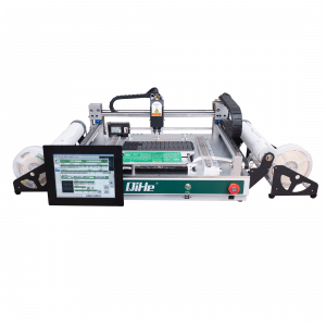
TVM802B Plus SMT pick and place machine 2heads 58slots desktop pick&place deluxe edition
-
QM10 SMT pick and place machine 10heads 80slots Fully Automatic Chip mounter SMT Assembly
-
TVM802BX SMT pick and place machine 2heads 46slots desktop pnp mounter deluxe edition
-
QL41 SMT pick and place machine 4heads 8slots LED for 1.2meters led strip pick&place machine
-
Q8 SMT pick and place machine 8heads 80slots Fully Automatic Chip mounter SMT Assembly
What is SMT in engineering?
Surface mount technology is a part of the electronic assembly that deals with the mounting of electronic components to the surface of a PCB. Electronic components mounted this way are called surface-mounted devices (SMD). SMT was developed to minimize manufacturing costs while making efficient use of board space.Qihe SMT company develops and produces all kinds of SMT equipment suitable for world wide market, including pnp machine,reflow oven,stencil printer,pcb handling machines,and other products.
Small desktop pick and place machine TVM802A,TVM802B,TVM802AX,TVM802BX series suitable for beginners, for hobbiest or low vol usag.
Advanced level 4-head LED strip placement QL41 led machines and with rail universal series TVM925S,TVM926S,
Fully automatic 6-10-head placement QM61,QM62,QM81,QM10,machines, which are suitable for high volume mass production in factories.
Know more about us https://www.qhsmt.com/about-qihe-smt-equipment/
Follow us on social media https://www.facebook.com/Qihesmt/
What is SMT in programming?
Offline Automated Programming vs Inline SMT Programming
Qihe pick and place machine can be programmed directly on the SMT equipment .
Or Coordinates can also be imported csv file through programming software.
Currently supported software such as protel,DXP,Altium Designer,Pads,Candes,proteus,DXP.
Inline SMT programming is a solution to consider for narrow segments of device programming requiring short programming times, with medium to high volume, for just one device type.
WHAT IS SMT pick and place machine?
SMT (Surface Mounted Technology) is a comprehensive system engineering technology, which covers substrates, design, equipment, components, assembly processes, production accessories and management. When it comes to SMT pick and place machines, the automatic SMT production line requires automatic loading and unloading machine, automatic solder paste printing machine, placement machine, reflow soldering machine, AOI inspection equipment, conveyor,connecting table, etc. For these SMT assembly line equipment, Qihe SMT can offer you machines in prototype SMT line, small SMT production line, mass production SMT line at low SMT line cost. Contact us now if you are interested.
WHAT IS SMT ASSEMBLY LINE?
With the development of technology, future electronic products will be lighter, smaller and thinner. Traditional assembly technology can no longer meet the requirements of high-precision and high-density assembly. A new type of PCB assembly technology-SMT (Surface Mount Technology) has emerged. SMT Assembly is the use of automated machines to assemble electronic components on the surface of the circuit board. Its density, high speed, standardization and other characteristics occupies an absolute advantage in the field of circuit assembly technology. In addition, SMT assembly has a wide range of uses.
https://www.qhsmt.com/fully-automatic-smt-pick-and-place-machine-line/

