After the advent of the LED era, we can see its presence in various aspects of life, whether in the automotive, intelligent, or industrial fields. Due to its high efficiency, energy conservation, long lifespan, environmental protection and other characteristics, it has become an optional solution for today’s lighting technology and is gradually being applied to lighting. A key factor driving people’s attention to LED lighting technology is that it greatly reduces energy consumption and enables long-term reliable operation. Today, qihe led machine will provide an extended introduction to LED lighting driver circuits from a practical LED circuit.
This article starts with a circuit that uses a constant current source. The main component in this circuit is the transistor, which requires a high power transistor with a withstand voltage of over 400V and a power of over 10W, such as MJE13003, MJE13005, etc., and a heat sink. The filtering capacitor C has a capacity of 4.7uF and a withstand voltage of over 400V. The current of the light emitting diode is determined by R2 adjustment. For convenience in adjustment, a variable resistor can be used to adjust and then replace it with a fixed resistor with the same resistance value, This circuit can carry as few as ten light-emitting diodes, with a maximum of more than 90. Although it increases some costs, the usage effect is much better than that of a circuit that only uses resistance current limiting. Even if the voltage fluctuation is large, the circuit can still maintain a constant current, which is very beneficial for the lifespan of the light-emitting diode. Within this range, the current can be basically kept constant. The number of light-emitting tubes used in this circuit should not be too small, as the smaller the number, the lower the efficiency. The total power consumption of this circuit is about 6W.
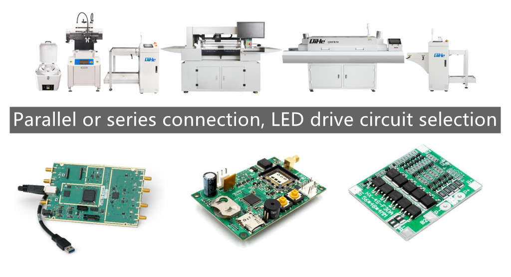
Would it be better to use parallel connection or series connection for LEDs?
LED adopts parallel or series connection method, mainly determined by the form and requirements of the power box circuit.
A circuit using a series connection method, when one of the LEDs is disconnected, the entire string of LEDs does not light up; But when one LED is short circuited, all other LEDs can still light up. A circuit using parallel connection method, when one LED is disconnected, all other LEDs can still light up; But when one of the LEDs is short circuited, the power supply of the entire circuit will be short circuited, which not only prevents the other LEDs from working properly, but also may damage the power supply. Therefore, compared to the series connection method, the circuit has more advantages.
The parallel connection method only requires a lower voltage to be applied at both ends of each LED, but requires the use of a ballast resistor or current source to ensure that the brightness of each LED is consistent. If the bias current flowing through each LED is different, their brightness will also be different, resulting in uneven brightness of the entire light source. However, using a ballast resistor or current source to ensure consistent LED brightness will shorten the battery’s lifespan. The use of series connection method can essentially ensure the consistency of the current flowing through each LED, but it requires a high power supply voltage. When LEDs are connected in parallel, the total current of the circuit is the sum of the currents of each LED, so it is required that the power supply be able to supply sufficient current.
In fact, strictly speaking, parallel or series connection methods have their own advantages and disadvantages. You need to consider multiple factors in practical application. In practical applications, LED arrays formed in series and parallel are often used to overcome or reduce the impact of single LED open circuit or short circuit on the entire circuit and power supply. The so-called series parallel connection refers to using a small number of LEDs in series and then serializing the ballast resistor to form a branch, and then connecting several branches in parallel to form a “branch group”. In addition, a series parallel connection can also be used, which is to connect several “branch groups” in series on the basis of the already formed “branch group” to form the entire lamp circuit. This connection not only reduces the impact surface of an LED fault, but also reduces the ballast resistance to zero, turning several high-power resistors into dozens of low-power resistors, and changing from centralized installation to decentralized installation, which is not only conducive to resistance heat dissipation, It is also possible to design the lighting fixtures more compactly.
Firstly, we must consider the power drive of any circuit. Usually, LED is driven by a dedicated constant current source or driver chip, which is easily limited by factors such as volume and cost. The most economical and practical method is to use a capacitive step-down power supply. Using it to drive low-power LEDs has the advantages of not being afraid of load short circuits and simple circuits, Moreover, one circuit can drive 1~70 low-power LEDs (however, the current impact of this power circuit during startup, especially frequent startup, will cause damage to LEDs. Of course, this impact can be avoided by taking appropriate protection. In this regard, the NUD4700 LED shunt protection solution of Onsemi Semiconductor can be used. When LEDs work normally, the leakage current is only about 100 μ A; When encountering transient or surge conditions, the LED will open circuit, and the shunt channel where the NUD4700 shunt protector is located will activate, resulting in a voltage drop of only 1.0 V, which will minimize the impact on the circuit as much as possible. This device adopts a space saving small package designed for 1 W LED (rated current 350 mA @ 3 V), and if heat dissipation treatment is appropriate, it also supports operations with a current greater than 1 A.
Typical Circuit of Capacitor Step-down Power Supply
For the inspection of the driving circuit, it is necessary to carefully check whether the circuit is connected incorrectly according to the circuit diagram. Special attention should be paid to checking the polarity of the rectifier bridge (the long leg is the positive output, the diagonal is the negative output, and the other two legs are the AC input), the rectifier diode, and the voltage regulator diode (the end printed with a black or white line is the negative), as well as checking whether the three electrodes of the crystal transistor or voltage regulator integrated circuit are connected incorrectly.
C1 is a step-down capacitor (using metallized polypropylene capacitors), and R1 provides a discharge circuit for C1. The capacitor C1 provides a constant working current for the entire circuit. Capacitance C2 is a Electrolytic capacitor, and its withstand voltage value depends on the number of LEDs connected in series (about 1.5 times of its total voltage). Its main function is to suppress the voltage jump caused by the instant of power on, so as to reduce the impact of voltage shock on LED life. R4 is the discharge resistance of capacitor C2, and its resistance value should increase appropriately with the increase of the number of LEDs.
Due to the fact that capacitive step-down power supply is a non isolated type of power supply, it generates a large amount of current, also known as surge current, at the moment of power on. In addition, due to the influence of external environment (such as lightning strikes), the power grid system can invade various surge signals, and some surges can cause LED damage. Therefore, to provide thermistor protection, it mainly includes Negative temperature coefficient thermistor protection (NTC thermistor, NTC is the abbreviation of Negative Temperature Coefficient) and positive temperature coefficient thermistor protection (PTC), and then transient voltage suppressor protection (TVS)
Negative temperature coefficient means negative temperature coefficient, which generally refers to semiconductor materials or components with large Negative temperature coefficient. The simplest and most effective way to limit surge current is to connect a NTC thermistor in series at the line input
The positive temperature coefficient current passes through the PTC thermistor, causing the temperature to rise, that is, the temperature of the heating body to rise. When the temperature of the Curie temperature is exceeded, the resistance increases, thereby limiting the increase of the current, so the decrease of the current causes the temperature of the element to drop, and the decrease of the resistance value causes the circuit current to increase, and the element temperature to rise again and again.
Transient voltage suppressors are mainly used for fast overvoltage protection of circuit components. When the two poles of the TVS tube are impacted by the reverse transient high energy, it can change the high impedance between the two poles into a very low impedance at a speed of 10-12s, absorb the high energy surge, set the Voltage clamp between the two poles at a predetermined value, and protect the components in the electronic circuit from the impact of various surge pulses.
Best seller SMT Machine :Qihe smt line products
-
 SMT semi-automatic pick and place machine with Dispenser
 -
TVM925 SMT pick and place machine 4 head 38 feeders slots assembly of electronic components
-
Q10 SMT Automatic pick and place machine 10 Heads 100 Slots High Precision and High Efficiency SMT/LED Assembly
-
Q6 SMT pick and place machine 6heads 50slots With PCB Rail Servo Pick&Place Machine
-
Q4 SMT pick and place machine 4heads 50slots With PCB Rail Servo Pick&Place Machine
-
TVM802B Plus SMT pick and place machine 2heads 58slots desktop pick&place deluxe edition
-
QM10 SMT pick and place machine 10heads 80slots Fully Automatic Chip mounter SMT Assembly
-
TVM802BX SMT pick and place machine 2heads 46slots desktop pnp mounter deluxe edition
-
QL41 SMT pick and place machine 4heads 8slots LED for 1.2meters led strip pick&place machine


What is SMT in engineering?
Surface mount technology is a part of the electronic assembly that deals with the mounting of electronic components to the surface of a PCB. Electronic components mounted this way are called surface-mounted devices (SMD). SMT was developed to minimize manufacturing costs while making efficient use of board space.Qihe SMT company develops and produces all kinds of SMT equipment suitable for world wide market, including pnp machine,reflow oven,stencil printer,pcb handling machines,and other products.
Small desktop pick and place machine TVM802A,TVM802B,TVM802AX,TVM802BX series suitable for beginners, for hobbiest or low vol usag.
Advanced level 4-head LED strip placement QL41 led machines and with rail universal series TVM925S,TVM926S,
Fully automatic 6-10-head placement QM61,QM62,QM81,QM10,machines, which are suitable for high volume mass production in factories.
Know more about us https://www.qhsmt.com/about-qihe-smt-equipment/
Follow us on social media https://www.facebook.com/Qihesmt/
What is SMT in programming?
Offline Automated Programming vs Inline SMT Programming
Qihe pick and place machine can be programmed directly on the SMT equipment .
Or Coordinates can also be imported csv file through programming software.
Currently supported software such as protel,DXP,Altium Designer,Pads,Candes,proteus,DXP.
Inline SMT programming is a solution to consider for narrow segments of device programming requiring short programming times, with medium to high volume, for just one device type.
WHAT IS SMT pick and place machine?
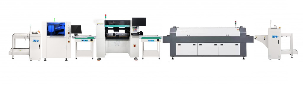
SMT (Surface Mounted Technology) is a comprehensive system engineering technology, which covers substrates, design, equipment, components, assembly processes, production accessories and management. When it comes to SMT pick and place machines, the automatic SMT production line requires automatic loading and unloading machine, automatic solder paste printing machine, placement machine, reflow soldering machine, AOI inspection equipment, conveyor,connecting table, etc. For these SMT assembly line equipment, Qihe SMT can offer you machines in prototype SMT line, small SMT production line, mass production SMT line at low SMT line cost. Contact us now if you are interested.
WHAT IS SMT ASSEMBLY LINE?
With the development of technology, future electronic products will be lighter, smaller and thinner. Traditional assembly technology can no longer meet the requirements of high-precision and high-density assembly. A new type of PCB assembly technology-SMT (Surface Mount Technology) has emerged. SMT Assembly is the use of automated machines to assemble electronic components on the surface of the circuit board. Its density, high speed, standardization and other characteristics occupies an absolute advantage in the field of circuit assembly technology. In addition, SMT assembly has a wide range of uses.
https://www.qhsmt.com/fully-automatic-smt-pick-and-place-machine-line/