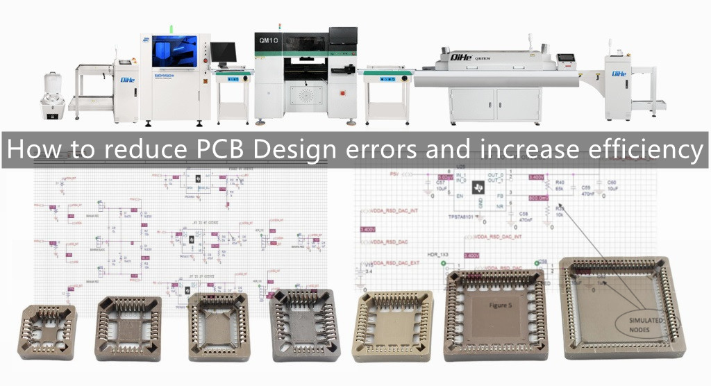
PCB circuit board design is a critical and time-consuming task, and any problems require engineers to check the entire design network by network and component by component. It can be said that circuit board design requires as much care as chip design. today qihe smt machine will discuss you with how to design PCB to reduce errors and improve efficiency?
A typical board design flow consists of the following steps:
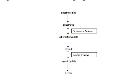
The first three stages take maximum time because the schematic review is a manual activity. Imagine a SoC board with 1000 or more connections. Reviewing each and every connection manually is a tedious task. It is almost impossible to check each, and this leads to problems in the final board, like wrong connections, floating nodes, etc.
The schematic capture phase generally faces the following types of problems:
Underscore errors: such as APLLVDD and APLL_VDD
● Capitalization issues: such as VDDE and vdde
● typos
● Signal short circuit problem
● …and many more
In order to avoid these mistakes, PCB design should have a way to check the entire schematic in a few seconds. This approach can be implemented using schematic simulation, which is rarely seen in current board design flows. Schematic simulation allows viewing of the final output at the required nodes, so it automatically checks for any connection problems.
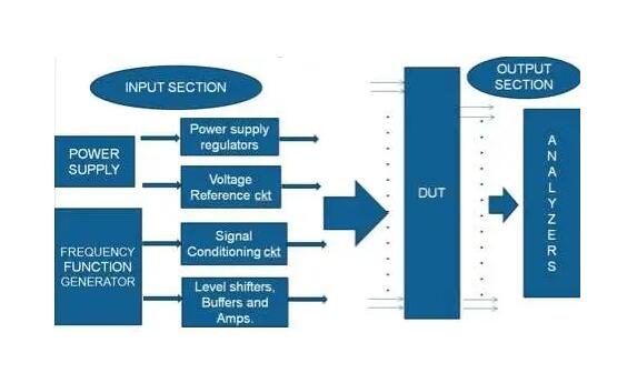
The following is explained through a project example. Consider a typical block diagram of a circuit board:
In a complex board design, the number of connections may reach thousands, and a very small number of changes is likely to waste many hours of checking.
Schematic simulation not only saves design time, but also improves board quality and increases the efficiency of the entire process.
A typical device under test (DUT) has some of the following signals:
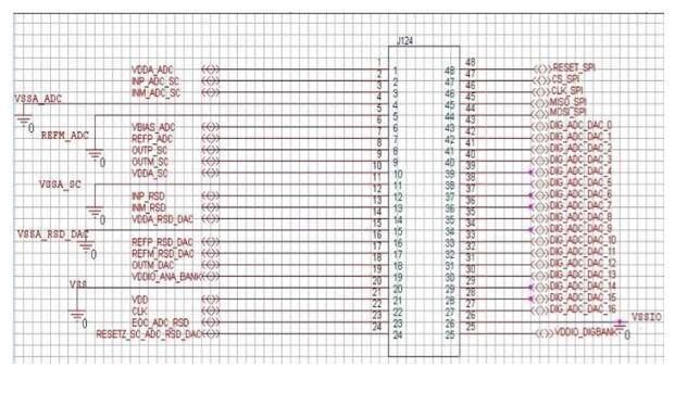
The device under test will have a variety of signals after some pre-conditioning, and there are various modules, such as voltage regulators, op amps, etc., for signal conditioning. Consider an example supply signal obtained through a voltage regulator.
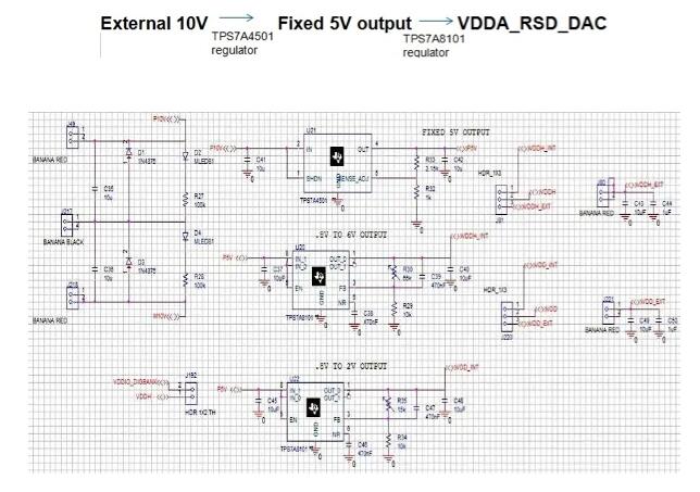
To verify connection relationships and perform overall checks, schematic simulation is used. Schematic simulation consists of schematic creation, testbench creation, and simulation.
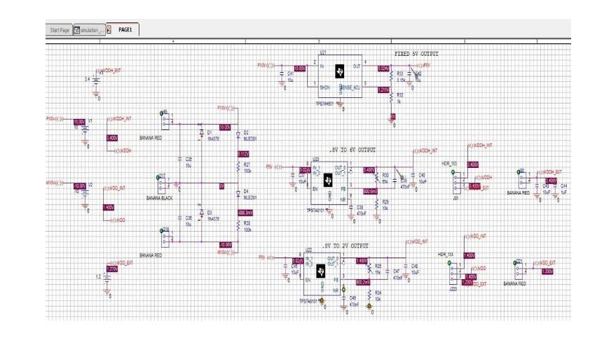
During testbench creation, stimulus signals are fed to the necessary inputs and outputs are observed at signal points of interest.
The above process can be realized by connecting the probe to the node to be observed. Node voltages and waveforms can indicate whether the schematic has errors. All signal connections are checked automatically.
Let’s take a look at a fragment of the image above, where the probed nodes and voltages are clearly visible:
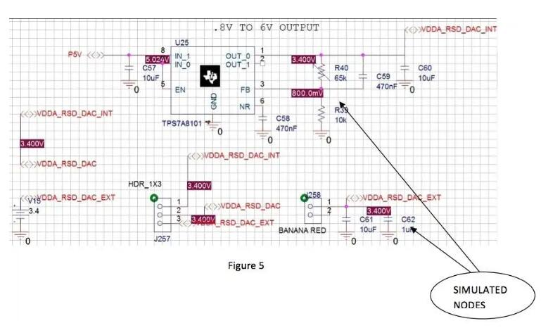
So with the help of simulation, we can directly observe the results and confirm that the board schematic is correct. In addition, investigation of design changes is enabled by careful adjustment of stimulus signals or component values. Schematic simulation can thus save board design and inspection personnel a lot of time and increase the chances of correct design.
Read more: How to reduce PCB Design errors and increase efficiencyBest seller SMT Machine :Qihe smt line products
-
 SMT semi-automatic pick and place machine with Dispenser
 -
TVM925 SMT pick and place machine 4 head 38 feeders slots assembly of electronic components
-
Q10 SMT Automatic pick and place machine 10 Heads 100 Slots High Precision and High Efficiency SMT/LED Assembly
-
Q6 SMT pick and place machine 6heads 50slots With PCB Rail Servo Pick&Place Machine
-
Q4 SMT pick and place machine 4heads 50slots With PCB Rail Servo Pick&Place Machine
-
TVM802B Plus SMT pick and place machine 2heads 58slots desktop pick&place deluxe edition
-
QM10 SMT pick and place machine 10heads 80slots Fully Automatic Chip mounter SMT Assembly
-
TVM802BX SMT pick and place machine 2heads 46slots desktop pnp mounter deluxe edition
-
QL41 SMT pick and place machine 4heads 8slots LED for 1.2meters led strip pick&place machine


What is SMT in engineering?
Surface mount technology is a part of the electronic assembly that deals with the mounting of electronic components to the surface of a PCB. Electronic components mounted this way are called surface-mounted devices (SMD). SMT was developed to minimize manufacturing costs while making efficient use of board space.Qihe SMT company develops and produces all kinds of SMT equipment suitable for world wide market, including pnp machine,reflow oven,stencil printer,pcb handling machines,and other products.
Small desktop pick and place machine TVM802A,TVM802B,TVM802AX,TVM802BX series suitable for beginners, for hobbiest or low vol usag.
Advanced level 4-head LED strip placement QL41 led machines and with rail universal series TVM925S,TVM926S,
Fully automatic 6-10-head placement QM61,QM62,QM81,QM10,machines, which are suitable for high volume mass production in factories.
Know more about us https://www.qhsmt.com/about-qihe-smt-equipment/
Follow us on social media https://www.facebook.com/Qihesmt/
What is SMT in programming?
Offline Automated Programming vs Inline SMT Programming
Qihe pick and place machine can be programmed directly on the SMT equipment .
Or Coordinates can also be imported csv file through programming software.
Currently supported software such as protel,DXP,Altium Designer,Pads,Candes,proteus,DXP.
Inline SMT programming is a solution to consider for narrow segments of device programming requiring short programming times, with medium to high volume, for just one device type.
WHAT IS SMT pick and place machine?
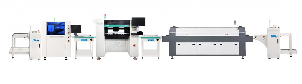
SMT (Surface Mounted Technology) is a comprehensive system engineering technology, which covers substrates, design, equipment, components, assembly processes, production accessories and management. When it comes to SMT pick and place machines, the automatic SMT production line requires automatic loading and unloading machine, automatic solder paste printing machine, placement machine, reflow soldering machine, AOI inspection equipment, conveyor,connecting table, etc. For these SMT assembly line equipment, Qihe SMT can offer you machines in prototype SMT line, small SMT production line, mass production SMT line at low SMT line cost. Contact us now if you are interested.
WHAT IS SMT ASSEMBLY LINE?
With the development of technology, future electronic products will be lighter, smaller and thinner. Traditional assembly technology can no longer meet the requirements of high-precision and high-density assembly. A new type of PCB assembly technology-SMT (Surface Mount Technology) has emerged. SMT Assembly is the use of automated machines to assemble electronic components on the surface of the circuit board. Its density, high speed, standardization and other characteristics occupies an absolute advantage in the field of circuit assembly technology. In addition, SMT assembly has a wide range of uses.
https://www.qhsmt.com/fully-automatic-smt-pick-and-place-machine-line/