Before explaining the inspection work after the PCB wiring is completed, I will introduce three special wiring techniques for PCB. The routing of PCB LAYOUT will be explained from three aspects: right-angle routing, differential routing, and serpentine routing.Today author from QiHe smt pick and place machine discussing about it with you .
Right-angle routing (three aspects)
The impact of the right-angle trace on the signal is mainly reflected in three aspects: first, the corner can be equivalent to a capacitive load on the transmission line, slowing down the rise time; second, the impedance discontinuity will cause signal reflection; third, the EMI generated by the right-angle tip. In the field of RF design above 10GHz, these small right angles may become the focus of high-speed problems.
Differential routing (“equal length, equidistant, reference plane”)
What is a differential signal? In layman’s terms, the driver sends two equal and inverted signals, and the receiver judges the logic state “0” or “1” by comparing the difference between the two voltages. The pair of traces that carry differential signals is called a differential trace. Compared with ordinary single-ended signal routing, differential signals have the most obvious advantages in the following three aspects:
1) Strong anti-interference ability, because the coupling between the two differential traces is very good, when there is noise interference from the outside world, they are coupled to the two lines almost at the same time, and the receiving end only cares about the difference between the two signals, so the external common mode noise can be completely offset.
2) It can effectively suppress EMI. For the same reason, because the polarities of the two signals are opposite, the electromagnetic fields radiated by them can cancel each other out. The tighter the coupling, the less electromagnetic energy is released to the outside world.
3) Timing positioning is accurate, because the switching change of the differential signal is located at the intersection of the two signals, unlike ordinary single-ended signals that rely on high and low threshold voltages to judge, so it is less affected by the process and temperature, can reduce timing errors, and is more suitable for circuits with low-amplitude signals. The currently popular LVDS (low voltage differential signaling) refers to this small-amplitude differential signaling technology.
Serpentine line (adjustment delay)
Serpentine lines are a type of wiring method often used in Layout. Its main purpose is to adjust the delay to meet the system timing design requirements. The two most critical parameters are the parallel coupling length (Lp) and the coupling distance (S). Obviously, when the signal is transmitted on the serpentine line, coupling will occur between the parallel segments, in the form of differential mode. The smaller the S, the larger the Lp, the greater the coupling degree. It may lead to a reduction in transmission delay and greatly reduce the quality of the signal due to crosstalk. The mechanism can refer to the analysis of common-mode and differential-mode crosstalk.
Here are some suggestions for pcb layout engineers when dealing with serpentine lines:
1) Try to increase the distance (S) of the parallel line segments, at least greater than 3H, where H refers to the distance from the signal trace to the reference plane. In layman’s terms, it means routing around a large bend. As long as S is large enough, mutual coupling effects can be almost completely avoided.
2) Reduce the coupling length Lp. When the delay of twice Lp approaches or exceeds the signal rise time, the generated crosstalk will reach saturation.
3) The signal transmission delay caused by the serpentine line of the strip line (Strip-Line) or the embedded microstrip line (Embedded Micro-strip) is smaller than that of the micro-strip line (Micro-strip). Theoretically, the stripline will not affect the transmission rate due to differential mode crosstalk.
4) For signal lines with high speed and strict timing requirements, try not to take serpentine lines, especially in a small area.
5) Serpentine wiring at any angle can be often used, which can effectively reduce mutual coupling.
6) In high-speed PCB design, the serpentine line has no so-called filtering or anti-interference ability, which can only reduce the signal quality, so it is only used for timing matching and has no other purpose.
7) Sometimes spiral routing can be considered for winding, and the simulation shows that its effect is better than that of normal serpentine routing.
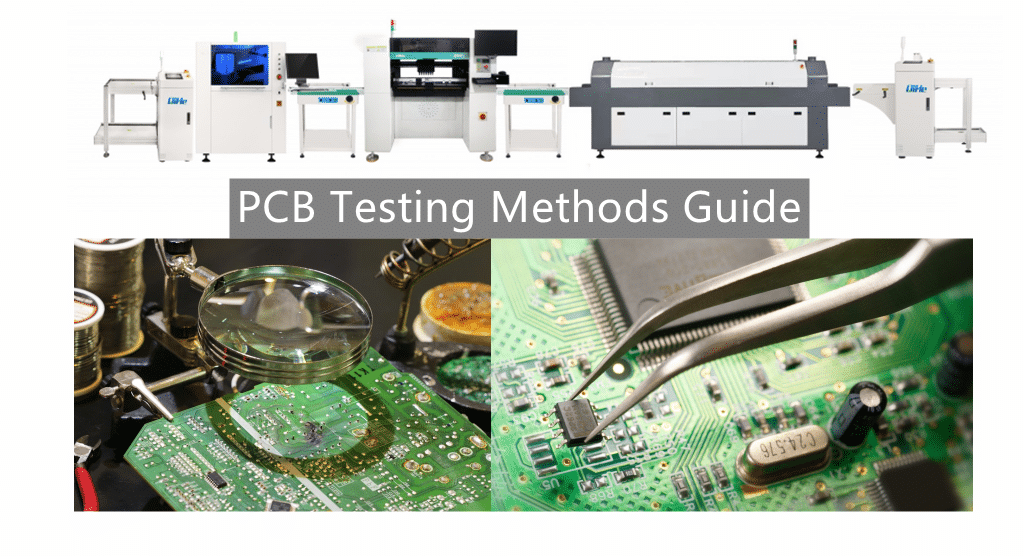
Read more: PCB Testing Methods Guide sharingBest seller SMT Machine :Qihe smt line products
-
 SMT semi-automatic pick and place machine with Dispenser
 -
TVM925 SMT pick and place machine 4 head 38 feeders slots assembly of electronic components
-
Q10 SMT Automatic pick and place machine 10 Heads 100 Slots High Precision and High Efficiency SMT/LED Assembly
-
Q6 SMT pick and place machine 6heads 50slots With PCB Rail Servo Pick&Place Machine
-
Q4 SMT pick and place machine 4heads 50slots With PCB Rail Servo Pick&Place Machine
-
TVM802B Plus SMT pick and place machine 2heads 58slots desktop pick&place deluxe edition
-
QM10 SMT pick and place machine 10heads 80slots Fully Automatic Chip mounter SMT Assembly
-
TVM802BX SMT pick and place machine 2heads 46slots desktop pnp mounter deluxe edition
-
QL41 SMT pick and place machine 4heads 8slots LED for 1.2meters led strip pick&place machine


What is SMT in engineering?
Surface mount technology is a part of the electronic assembly that deals with the mounting of electronic components to the surface of a PCB. Electronic components mounted this way are called surface-mounted devices (SMD). SMT was developed to minimize manufacturing costs while making efficient use of board space.Qihe SMT company develops and produces all kinds of SMT equipment suitable for world wide market, including pnp machine,reflow oven,stencil printer,pcb handling machines,and other products.
Small desktop pick and place machine TVM802A,TVM802B,TVM802AX,TVM802BX series suitable for beginners, for hobbiest or low vol usag.
Advanced level 4-head LED strip placement QL41 led machines and with rail universal series TVM925S,TVM926S,
Fully automatic 6-10-head placement QM61,QM62,QM81,QM10,machines, which are suitable for high volume mass production in factories.
Know more about us https://www.qhsmt.com/about-qihe-smt-equipment/
Follow us on social media https://www.facebook.com/Qihesmt/
What is SMT in programming?
Offline Automated Programming vs Inline SMT Programming
Qihe pick and place machine can be programmed directly on the SMT equipment .
Or Coordinates can also be imported csv file through programming software.
Currently supported software such as protel,DXP,Altium Designer,Pads,Candes,proteus,DXP.
Inline SMT programming is a solution to consider for narrow segments of device programming requiring short programming times, with medium to high volume, for just one device type.
WHAT IS SMT pick and place machine?
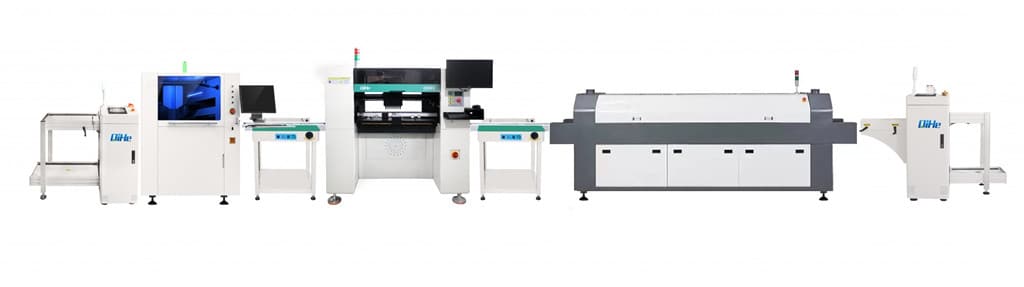
SMT (Surface Mounted Technology) is a comprehensive system engineering technology, which covers substrates, design, equipment, components, assembly processes, production accessories and management. When it comes to SMT pick and place machines, the automatic SMT production line requires automatic loading and unloading machine, automatic solder paste printing machine, placement machine, reflow soldering machine, AOI inspection equipment, conveyor,connecting table, etc. For these SMT assembly line equipment, Qihe SMT can offer you machines in prototype SMT line, small SMT production line, mass production SMT line at low SMT line cost. Contact us now if you are interested.
WHAT IS SMT ASSEMBLY LINE?
With the development of technology, future electronic products will be lighter, smaller and thinner. Traditional assembly technology can no longer meet the requirements of high-precision and high-density assembly. A new type of PCB assembly technology-SMT (Surface Mount Technology) has emerged. SMT Assembly is the use of automated machines to assemble electronic components on the surface of the circuit board. Its density, high speed, standardization and other characteristics occupies an absolute advantage in the field of circuit assembly technology. In addition, SMT assembly has a wide range of uses.
https://www.qhsmt.com/fully-automatic-smt-pick-and-place-machine-line/