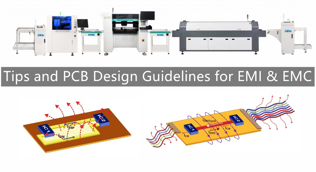
The sensitivity of electronic equipment is getting higher and higher, which requires the anti-interference ability of the equipment to be stronger and stronger, so PCB design has become more difficult. How to improve the anti-interference ability of PCB has become one of the key issues concerned by many engineers. This article will introduce some tips for reducing noise and electromagnetic interference in PCB design. Today qihe smt pick and place machine will share some tips for reducing noise and electromagnetic interference in PCB design
(1) If you can use low-speed chips, you don’t need high-speed ones. High-speed chips are used in key places.
(2) A resistor can be connected in series to reduce the jump rate of the upper and lower edges of the control circuit.
(3) Try to provide some form of damping for relays etc.
(4) Use the lowest frequency clock that meets the system requirements.
(5) The clock generator should be as close as possible to the device using the clock. The shell of the quartz crystal oscillator should be grounded.
(6) Use the ground wire to encircle the clock area, and keep the clock wire as short as possible.
(7) The I/O drive circuit should be as close to the edge of the printed board as possible, so that it can leave the printed board as soon as possible. The signal entering the printed board should be filtered, and the signal coming from the high-noise area should also be filtered. At the same time, the method of connecting terminal resistors should be used to reduce signal reflection.
(8) The useless end of the MCD should be connected to high, or grounded, or defined as an output end, and the end of the integrated circuit that should be connected to the power ground must be connected, and should not be suspended.
(9) Do not suspend the input terminal of the unused gate circuit, the positive input terminal of the unused operational amplifier is grounded, and the negative input terminal is connected to the output terminal.
(10) Printed boards use 45-fold instead of 90-fold wiring to reduce the external emission and coupling of high-frequency signals.
(11) The printed board is partitioned according to frequency and current switching characteristics, and the distance between noise components and non-noise components should be further.
(12) Single-panel and double-panel use single-point power supply and single-point grounding. The power line and ground line should be as thick as possible. If the economy is affordable, multi-layer boards should be used to reduce the inductance of the power supply and ground.
(13) Clock, bus, and chip select signals should be kept away from I/O lines and connectors.
(14) Analog voltage input lines and reference voltage terminals should be kept as far away as possible from digital circuit signal lines, especially clocks.
(15) For A/D devices, the digital part and the analog part should be unified rather than crossed.
(16) Clock lines perpendicular to I/O lines have less interference than parallel I/O lines, and clock component pins are far away from I/O cables.
(17) The component pins should be as short as possible, and the decoupling capacitor pins should be as short as possible.
(18) The key line should be as thick as possible, and protection ground should be added on both sides. High-speed lines should be short and straight.
(19) Noise-sensitive lines should not be paralleled with high-current, high-speed switching lines.
(20) Do not route wires under the quartz crystal or under noise-sensitive devices.
(21) Weak signal circuit, do not form a current loop around the low frequency circuit.
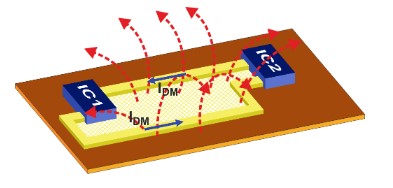
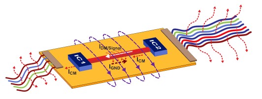
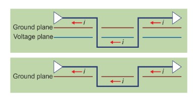
(22) The signal should not form a loop. If it is unavoidable, make the loop area as small as possible.
(23) One decoupling capacitor per IC. A small high-frequency bypass capacitor should be added next to each electrolytic capacitor.
(24) Use large-capacity tantalum capacitors or polycool capacitors instead of electrolytic capacitors as circuits to charge and discharge energy storage capacitors. When using tubular capacitors, the case should be grounded.
Read more: Tips and PCB Design Guidelines for EMI & EMCBest seller SMT Machine :Qihe smt line products
-
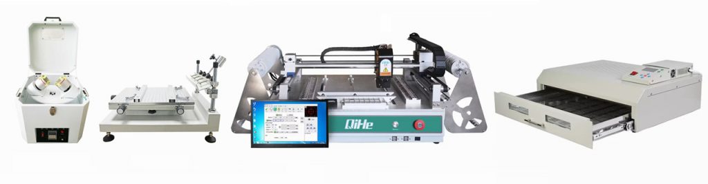
 SMT semi-automatic pick and place machine with Dispenser
 -
TVM925 SMT pick and place machine 4 head 38 feeders slots assembly of electronic components
-
Q10 SMT Automatic pick and place machine 10 Heads 100 Slots High Precision and High Efficiency SMT/LED Assembly
-
Q6 SMT pick and place machine 6heads 50slots With PCB Rail Servo Pick&Place Machine
-
Q4 SMT pick and place machine 4heads 50slots With PCB Rail Servo Pick&Place Machine
-
TVM802B Plus SMT pick and place machine 2heads 58slots desktop pick&place deluxe edition
-
QM10 SMT pick and place machine 10heads 80slots Fully Automatic Chip mounter SMT Assembly
-
TVM802BX SMT pick and place machine 2heads 46slots desktop pnp mounter deluxe edition
-
QL41 SMT pick and place machine 4heads 8slots LED for 1.2meters led strip pick&place machine


What is SMT in engineering?
Surface mount technology is a part of the electronic assembly that deals with the mounting of electronic components to the surface of a PCB. Electronic components mounted this way are called surface-mounted devices (SMD). SMT was developed to minimize manufacturing costs while making efficient use of board space.Qihe SMT company develops and produces all kinds of SMT equipment suitable for world wide market, including pnp machine,reflow oven,stencil printer,pcb handling machines,and other products.
Small desktop pick and place machine TVM802A,TVM802B,TVM802AX,TVM802BX series suitable for beginners, for hobbiest or low vol usag.
Advanced level 4-head LED strip placement QL41 led machines and with rail universal series TVM925S,TVM926S,
Fully automatic 6-10-head placement QM61,QM62,QM81,QM10,machines, which are suitable for high volume mass production in factories.
Know more about us https://www.qhsmt.com/about-qihe-smt-equipment/
Follow us on social media https://www.facebook.com/Qihesmt/
What is SMT in programming?
Offline Automated Programming vs Inline SMT Programming
Qihe pick and place machine can be programmed directly on the SMT equipment .
Or Coordinates can also be imported csv file through programming software.
Currently supported software such as protel,DXP,Altium Designer,Pads,Candes,proteus,DXP.
Inline SMT programming is a solution to consider for narrow segments of device programming requiring short programming times, with medium to high volume, for just one device type.
WHAT IS SMT pick and place machine?
SMT (Surface Mounted Technology) is a comprehensive system engineering technology, which covers substrates, design, equipment, components, assembly processes, production accessories and management. When it comes to SMT pick and place machines, the automatic SMT production line requires automatic loading and unloading machine, automatic solder paste printing machine, placement machine, reflow soldering machine, AOI inspection equipment, conveyor,connecting table, etc. For these SMT assembly line equipment, Qihe SMT can offer you machines in prototype SMT line, small SMT production line, mass production SMT line at low SMT line cost. Contact us now if you are interested.
WHAT IS SMT ASSEMBLY LINE?
With the development of technology, future electronic products will be lighter, smaller and thinner. Traditional assembly technology can no longer meet the requirements of high-precision and high-density assembly. A new type of PCB assembly technology-SMT (Surface Mount Technology) has emerged. SMT Assembly is the use of automated machines to assemble electronic components on the surface of the circuit board. Its density, high speed, standardization and other characteristics occupies an absolute advantage in the field of circuit assembly technology. In addition, SMT assembly has a wide range of uses.
https://www.qhsmt.com/fully-automatic-smt-pick-and-place-machine-line/