The power ground is mainly for the path of the power loop current. Generally speaking, the current flowing through the power ground is relatively large, while the signal ground is mainly for the return flow of the communication signal between two chips or modules. Path, generally speaking, the current flowing through the signal ground is very small. In fact, both are GND. The reason why they are separated is to let everyone understand that when laying out the PCB board, it is necessary to clearly understand the flow of the power supply and the signal return flow. path, and then consider how to avoid the common return path of power supply and signal when laying out the board. If it is shared, it may cause a large current on the power supply ground to generate a voltage difference on the signal ground (it can be interpreted as: the wire has impedance, but A small resistance value, but if the current flowing through is large, a potential difference will also be generated on this wire, which is also called common impedance interference), so that the real potential of the signal ground is higher than 0V, if the potential of the signal ground When it is larger, it may cause the signal to be high level, but it is misjudged as low level.Today qihe smt pick and place machine will share some knowledge about it.
Of course, the ground of the power supply is inherently dirty, and doing so also avoids signal misjudgment due to interference. So just pay attention to the two grounds when wiring. Generally speaking, even together, there will be no major problems, because the threshold of digital circuits is relatively high. In addition to the correct grounding design and installation, it is also necessary to correctly perform the grounding treatment of various signals. In the control system, there are roughly the following ground wires:
(1) Digital ground: also called logic ground, it is the zero potential of various switching (digital) signals.
(2) Analog ground: It is the zero potential of various analog signals.
(3) Signal ground: usually the ground of the sensor.
(4) AC ground: the ground wire of the AC power supply, which is usually the ground that generates noise.
(5) DC ground: the ground of the DC power supply.
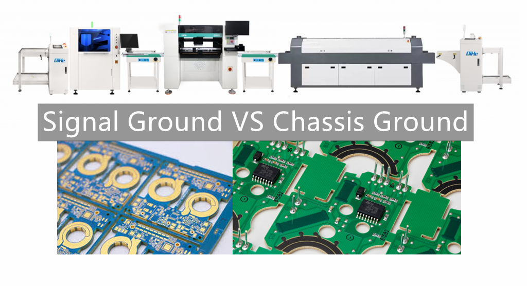
(6) Shielding ground: also called chassis ground, it is designed to prevent electrostatic induction and magnetic field induction.
The handling of the above ground wires is an important issue in system design, installation and commissioning. Here are some ideas on grounding issues:
(1) The control system should be grounded at one point. In general, high-frequency circuits should be grounded at multiple points nearby, and low-frequency circuits should be grounded at one point. In low-frequency circuits, the inductance between wiring and components is not a big problem, but the interference of the loop formed by grounding has a great influence, so one point is often used as the grounding point; but one point grounding is not suitable for high-frequency, because high-frequency When , there is inductance on the ground, which increases the impedance of the ground wire, and at the same time, inductive coupling occurs between the various wires. Generally speaking, if the frequency is below 1MHz, one-point grounding can be used; when it is higher than 10MHz, multi-point grounding can be used; between 1MHz and 10MHz, one-point grounding can be used, and multi-point grounding can also be used.
(2) The AC ground and the signal ground cannot be shared. Since there will be a voltage of several mV or even several V between two points of a power supply ground wire, this is a very important interference for low-level signal circuits, so it must be isolated and prevented.
(3) Comparison between floating and grounding. The whole machine is floating, that is, all parts of the system are floating with the ground. This method is simple, but the insulation resistance between the whole system and the ground should not be less than 50MΩ. This method has a certain anti-interference ability, but once the insulation drops, it will cause interference. Another way is to ground the case and leave the rest floating. This method has strong anti-interference ability, safe and reliable, but it is more complicated to realize.
(4) Analog ground. The connection method of analog ground is very important. In order to improve the anti-common mode interference ability, shielding floating technology can be used for analog signals. The grounding treatment of specific analog signals should be designed in strict accordance with the requirements in the operation manual.
(5) Shielding ground. In the control system, in order to reduce the capacitive coupling noise in the signal, accurately detect and control, it is very necessary to adopt shielding measures for the signal. According to different shielding purposes, the connection method of shielding ground is also different. Electric field shielding solves the problem of distributed capacitance, and is generally connected to the ground; electromagnetic field shielding mainly avoids high-frequency electromagnetic field radiation interference such as radar and radio stations. It is made of low-resistance metal material with high conductivity and can be connected to the ground. Magnetic field shielding is used to prevent magnetic induction of magnets, motors, transformers, coils, etc. The shielding method is to use high magnetic permeability materials to close the magnetic circuit, and it is generally better to connect to the ground. When the signal circuit is grounded at one point, the shielding layer of the low-frequency cable should also be grounded at one point. If there is more than one location of the shielding layer of the cable, noise current will be generated and form a noise interference source. When a circuit has an ungrounded signal source connected to a grounded amplifier in the system, the shield at the input should be connected to the common of the amplifier; conversely, when a grounded signal source is connected to an ungrounded amplifier in the system, the amplifier’s input The terminal should also be connected to the common terminal of the signal source.
For the grounding of the electrical system, it should be classified according to the requirements and purposes of grounding. Different types of grounding cannot be simply and arbitrarily connected together, but should be divided into several independent grounding subsystems, and each subsystem has its common grounding point. Or the main grounding line, which is connected together at the end, and the general grounding is implemented.
Read more: Signal Ground VS Chassis GroundBest seller SMT Machine :Qihe smt line products
-
 SMT semi-automatic pick and place machine with Dispenser
 -
TVM925 SMT pick and place machine 4 head 38 feeders slots assembly of electronic components
-
Q10 SMT Automatic pick and place machine 10 Heads 100 Slots High Precision and High Efficiency SMT/LED Assembly
-
Q6 SMT pick and place machine 6heads 50slots With PCB Rail Servo Pick&Place Machine
-
Q4 SMT pick and place machine 4heads 50slots With PCB Rail Servo Pick&Place Machine
-
TVM802B Plus SMT pick and place machine 2heads 58slots desktop pick&place deluxe edition
-
QM10 SMT pick and place machine 10heads 80slots Fully Automatic Chip mounter SMT Assembly
-
TVM802BX SMT pick and place machine 2heads 46slots desktop pnp mounter deluxe edition
-
QL41 SMT pick and place machine 4heads 8slots LED for 1.2meters led strip pick&place machine


What is SMT in engineering?
Surface mount technology is a part of the electronic assembly that deals with the mounting of electronic components to the surface of a PCB. Electronic components mounted this way are called surface-mounted devices (SMD). SMT was developed to minimize manufacturing costs while making efficient use of board space.Qihe SMT company develops and produces all kinds of SMT equipment suitable for world wide market, including pnp machine,reflow oven,stencil printer,pcb handling machines,and other products.
Small desktop pick and place machine TVM802A,TVM802B,TVM802AX,TVM802BX series suitable for beginners, for hobbiest or low vol usag.
Advanced level 4-head LED strip placement QL41 led machines and with rail universal series TVM925S,TVM926S,
Fully automatic 6-10-head placement QM61,QM62,QM81,QM10,machines, which are suitable for high volume mass production in factories.
Know more about us https://www.qhsmt.com/about-qihe-smt-equipment/
Follow us on social media https://www.facebook.com/Qihesmt/
What is SMT in programming?
Offline Automated Programming vs Inline SMT Programming
Qihe pick and place machine can be programmed directly on the SMT equipment .
Or Coordinates can also be imported csv file through programming software.
Currently supported software such as protel,DXP,Altium Designer,Pads,Candes,proteus,DXP.
Inline SMT programming is a solution to consider for narrow segments of device programming requiring short programming times, with medium to high volume, for just one device type.
WHAT IS SMT pick and place machine?
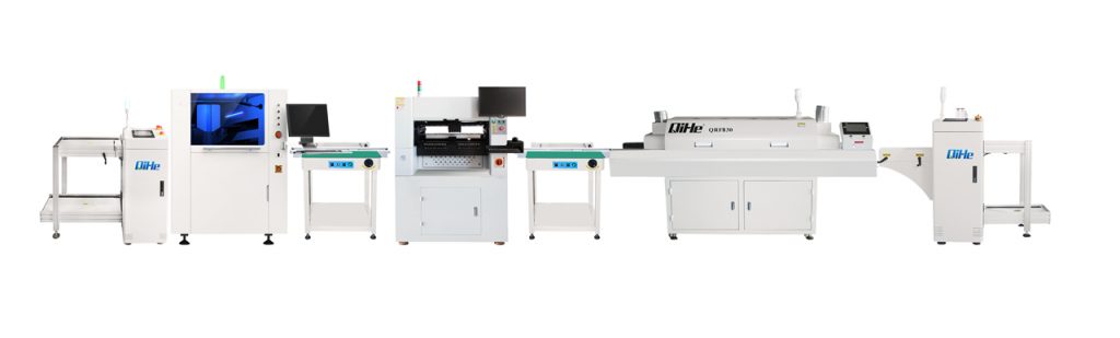
SMT (Surface Mounted Technology) is a comprehensive system engineering technology, which covers substrates, design, equipment, components, assembly processes, production accessories and management. When it comes to SMT pick and place machines, the automatic SMT production line requires automatic loading and unloading machine, automatic solder paste printing machine, placement machine, reflow soldering machine, AOI inspection equipment, conveyor,connecting table, etc. For these SMT assembly line equipment, Qihe SMT can offer you machines in prototype SMT line, small SMT production line, mass production SMT line at low SMT line cost. Contact us now if you are interested.
WHAT IS SMT ASSEMBLY LINE?
With the development of technology, future electronic products will be lighter, smaller and thinner. Traditional assembly technology can no longer meet the requirements of high-precision and high-density assembly. A new type of PCB assembly technology-SMT (Surface Mount Technology) has emerged. SMT Assembly is the use of automated machines to assemble electronic components on the surface of the circuit board. Its density, high speed, standardization and other characteristics occupies an absolute advantage in the field of circuit assembly technology. In addition, SMT assembly has a wide range of uses.
https://www.qhsmt.com/fully-automatic-smt-pick-and-place-machine-line/