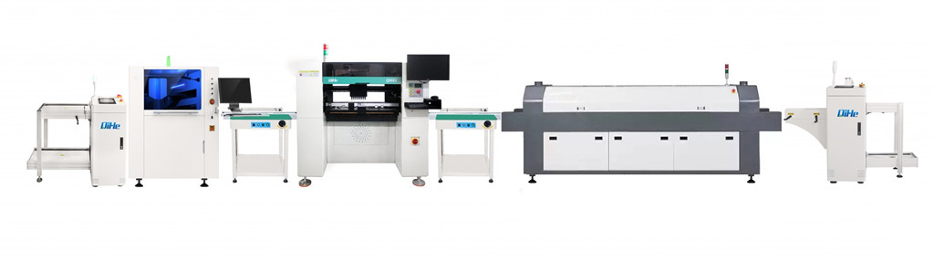
For the design of electromagnetic interference, we mainly design and process it from the aspects of hardware and software. Today qihe smt pick and place machine showing an introduction to the processing of electromagnetic compatibility from the PCB design of the single-chip microcomputer to the software processing.
Factors affecting EMC
- Voltage
Higher supply voltages mean larger voltage swings and more emissions, while low supply voltages affect sensitivity.
- frequency
High frequencies produce more emissions, periodic signals produce more emissions. In a high-frequency single-chip microcomputer system, a current spike signal is generated when the device switches; in an analog system, a current spike signal is generated when the load current changes.
- grounding
Among all EMC problems, the main problem is caused by improper grounding. There are three methods of signal grounding: single point, multipoint, and hybrid. When the frequency is lower than 1MHz, the single-point grounding method can be used, but it is not suitable for high frequency; in high-frequency applications, it is better to use multi-point grounding. Hybrid grounding is a method of single-point grounding for low frequencies and multi-point grounding for high frequencies. The ground layout is the key, and the ground circuits of high-frequency digital circuits and low-level analog circuits must not be mixed.
- PCB design
Proper printed circuit board (PCB) routing is critical to preventing EMI.
- power decoupling
When devices switch, transient currents are induced on the power supply lines that must be attenuated and filtered. Transient currents from high di/dt sources cause ground and trace “shoot” voltages, and the high di/dt produces wide-ranging high-frequency currents that excite components and cable radiation. The change in current through the wire and the inductance cause a voltage drop, which can be minimized by reducing the inductance or the change in current over time.
Hardware processing method for jamming measures
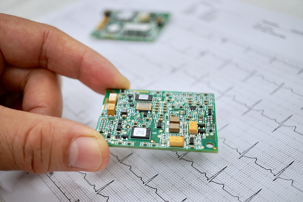
- Electromagnetic Compatibility Design of Printed Circuit Board (PCB)
The PCB is a support for circuit components and devices in a single-chip microcomputer system, and it provides electrical connections between circuit components and devices. With the rapid development of electronic technology, the density of PCB is getting higher and higher. The quality of PCB design has a great influence on the electromagnetic compatibility of the single-chip microcomputer system. Practice has proved that even if the circuit schematic design is correct and the printed circuit board is not properly designed, it will also have an adverse effect on the reliability of the single-chip microcomputer system. For example, if two thin parallel lines on a printed circuit board are placed in close proximity, there will be a delay in the signal waveform, causing reflection noise at the end of the transmission line. Therefore, when designing a printed circuit board, care should be taken to adopt the correct method, follow the general principles of PCB design, and meet the design requirements for anti-interference. To achieve the best performance of electronic circuits, the layout of components and the routing of wires are very important.
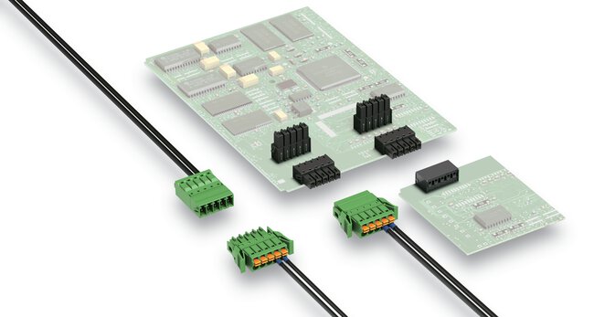
- EMC design of input/output
In the single-chip system, the input/output is also the conductive line of the interference source, and the pick-up source for receiving radio frequency interference signals. We generally need to take effective measures when designing:
① Use the necessary common mode/differential mode suppression circuit, and also take certain filtering and anti-electromagnetic shielding measures to reduce the entry of interference.
②When conditions permit, take various isolation measures (such as photoelectric isolation or magnetoelectric isolation) as much as possible, so as to block the propagation of interference.
- The Design of Single Chip Microcomputer Reset Circuit
In a single-chip microcomputer system, the watchdog system plays a particularly important role in the operation of the entire single-chip microcomputer. Since all sources of interference cannot be completely isolated or removed, once the CPU enters the normal operation of the interference program, then the reset system combined with Software handling measures become an effective error correction defense barrier. There are two commonly used reset systems:
①External reset system. The external “watchdog” circuit can be designed by yourself or built with a special “watchdog” chip. However, they have their own advantages and disadvantages. Most of the dedicated “watchdog” chips cannot respond to low-frequency “feeding dog” signals, but high-frequency “feeding dogs” signals can respond, making them generate The reset action does not occur under the high-frequency “feeding dog” signal. In this way, if the program system falls into an infinite loop, and there happens to be a “feeding dog” signal in the loop, then the reset circuit cannot realize it. It should function. However, we can design a system with a bandpass “feed dog” circuit and other reset circuits that is a very effective external monitoring system.
②Now more and more single-chip microcomputers have their own on-chip reset system, so that users can use the internal reset timer very conveniently. However, there are some types of single-chip microcomputers whose reset instructions are too simple. There will be a “feed the dog” command like the above-mentioned infinite loop, making it lose its monitoring function. Some single-chip microcomputer reset instructions are better. Generally, they make the “feed the dog” signal into multiple instructions in a fixed format and execute them sequentially. If there is a certain error, the “feed the dog” operation will be invalid, which greatly Improve the reliability of the reset circuit.
- oscillator
Most microcontrollers have an oscillator circuit coupled to an external crystal or ceramic resonator. On the PCB, the leads that require external capacitors, crystals or ceramic resonators are as short as possible. RC oscillators are latently sensitive to interfering signals and can generate very short clock periods, so crystal or ceramic resonators are the best choice. In addition, the shell of the quartz crystal should be grounded.
- Lightning protection measures
The single-chip microcomputer system used outdoors or the power line and signal line introduced from the outdoor to the indoor should consider the lightning protection problem of the system. Commonly used lightning protection devices include: gas discharge tube, TVS (Transient Voltage Suppression) and so on. The gas discharge tube is when the voltage of the power supply is greater than a certain value, usually tens of V or hundreds of V, the gas breaks down and discharges, and guides the strong impact pulse on the power line into the ground. TVS can be regarded as two Zener diodes connected in parallel and opposite in direction, which are turned on when the voltage across them is higher than a certain value. Its characteristic is that it can pass a current of hundreds or even thousands of A transiently.
Software Processing Method for Interference Measures
Interference signals generated by electromagnetic interference sources cannot be completely eliminated in some specific cases (such as in some harsh electromagnetic environments), and will eventually enter the core unit of CPU processing, so that in some large-scale integrated Circuits are often disturbed, causing them to not function properly or to operate in an incorrect state. In particular, devices such as RAM that use bistable states for storage tend to flip under strong interference, making the original stored “0” into “1”, or “1” into “0”; some serial The timing and data of transmission will be changed due to interference; more seriously, some important data parameters will be destroyed; the consequences are often very serious. In this case, the quality of software design directly affects the anti-interference ability of the whole system.
The program will generally encounter the following situations due to electromagnetic interference:
① The program runs away.
This situation is the most common interference result. Generally speaking, a good reset system or software frame test system is enough, and it will not have much impact on the entire operating system.
② Infinite loop or abnormal program code operation.
Of course, this kind of infinite loop and abnormal program code is not written intentionally by the designer. We know that the program instructions are composed of bytes, some are single-byte instructions and some are multi-byte instructions. When the interference occurs, the PC pointer will be broken. Changes, so that the original program code has been reorganized to produce unguessable executable program code, then this kind of error is fatal, it may modify important data parameters, and may produce unguessable control output and so on a series of error states.
- Measures for storage of important parameters
In general, we can use error detection and correction to effectively reduce or avoid this situation. According to the principle of error detection and error correction, the main idea is to generate a check code with a certain number of digits according to the written data when the data is written in, and save it together with the corresponding data; The code is read out and a judgment is made. If there is a one-bit error, it will be automatically corrected, the correct data will be sent out, and at the same time the corrected data will be written back to cover the original wrong data; if there is a two-bit error, an interrupt report will be generated and the CPU will be notified to handle the exception. All these actions are automatically completed by software design, and have the characteristics of real-time and automatic completion. Through such a design, the anti-interference ability of the system can be greatly improved, thereby improving the reliability of the system.
Error detection and error correction principle:
First, let’s look at the basic principles of error detection and error correction. The basic idea of error control is to add different redundant codes with certain rules in the information code group, so that when the information is read out, it can detect or automatically correct errors by relying on redundant monitoring codes or calibration codes.
Aiming at the characteristics of bit errors, that is, the randomness and arbitrariness of errors, it almost always randomly affects a certain bit in a byte. Therefore, if one bit error can be designed to automatically correct, and Check how the two bits are wrongly encoded. Can greatly improve the reliability of the system.
- Detection of RAM and FLASH (ROM)
When programming, we’d better write some detection programs to test the data codes of RAM and FLASH (ROM) to see if there are any errors. Once it occurs, it should be corrected immediately. deal with.
In addition, it is indispensable to add program redundancy when programming. Adding three or more NOP instructions in a certain place has a very effective preventive effect on program reorganization. At the same time, flag data and detection status should be introduced into the running state of the program, so that errors can be found and corrected in time.
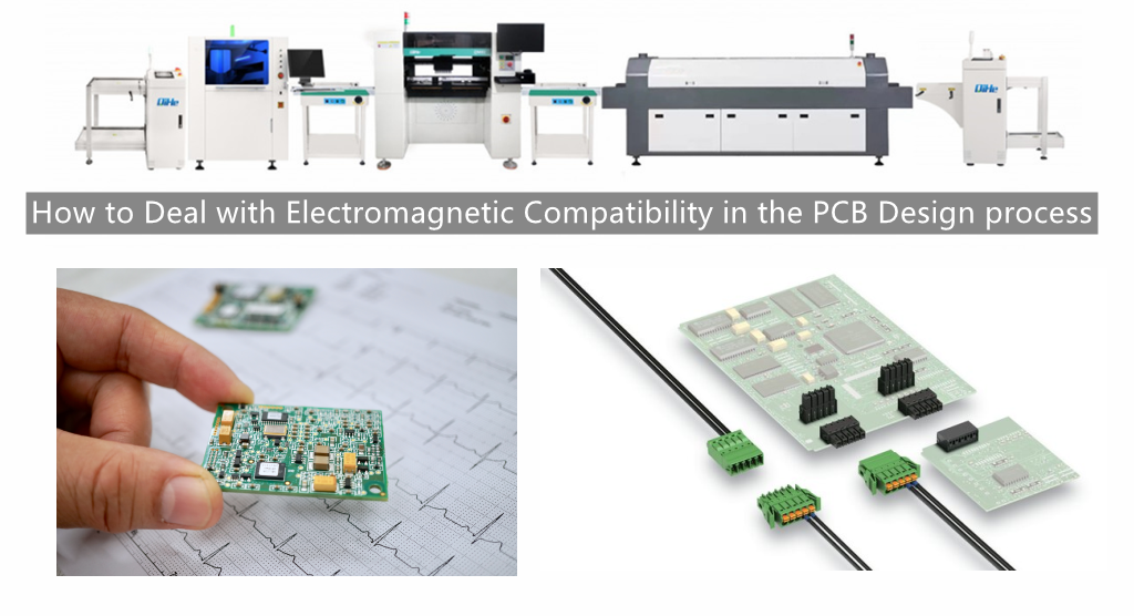
Read more: How to Deal with Electromagnetic Compatibility in the PCB Design processBest seller SMT Machine :Qihe smt line products
-
 SMT semi-automatic pick and place machine with Dispenser
 -
TVM925 SMT pick and place machine 4 head 38 feeders slots assembly of electronic components
-
Q10 SMT Automatic pick and place machine 10 Heads 100 Slots High Precision and High Efficiency SMT/LED Assembly
-
Q6 SMT pick and place machine 6heads 50slots With PCB Rail Servo Pick&Place Machine
-
Q4 SMT pick and place machine 4heads 50slots With PCB Rail Servo Pick&Place Machine
-
TVM802B Plus SMT pick and place machine 2heads 58slots desktop pick&place deluxe edition
-
QM10 SMT pick and place machine 10heads 80slots Fully Automatic Chip mounter SMT Assembly
-
TVM802BX SMT pick and place machine 2heads 46slots desktop pnp mounter deluxe edition
-
QL41 SMT pick and place machine 4heads 8slots LED for 1.2meters led strip pick&place machine


What is SMT in engineering?
Surface mount technology is a part of the electronic assembly that deals with the mounting of electronic components to the surface of a PCB. Electronic components mounted this way are called surface-mounted devices (SMD). SMT was developed to minimize manufacturing costs while making efficient use of board space.Qihe SMT company develops and produces all kinds of SMT equipment suitable for world wide market, including pnp machine,reflow oven,stencil printer,pcb handling machines,and other products.
Small desktop pick and place machine TVM802A,TVM802B,TVM802AX,TVM802BX series suitable for beginners, for hobbiest or low vol usag.
Advanced level 4-head LED strip placement QL41 led machines and with rail universal series TVM925S,TVM926S,
Fully automatic 6-10-head placement QM61,QM62,QM81,QM10,machines, which are suitable for high volume mass production in factories.
Know more about us https://www.qhsmt.com/about-qihe-smt-equipment/
Follow us on social media https://www.facebook.com/Qihesmt/
What is SMT in programming?
Offline Automated Programming vs Inline SMT Programming
Qihe pick and place machine can be programmed directly on the SMT equipment .
Or Coordinates can also be imported csv file through programming software.
Currently supported software such as protel,DXP,Altium Designer,Pads,Candes,proteus,DXP.
Inline SMT programming is a solution to consider for narrow segments of device programming requiring short programming times, with medium to high volume, for just one device type.
WHAT IS SMT pick and place machine?
SMT (Surface Mounted Technology) is a comprehensive system engineering technology, which covers substrates, design, equipment, components, assembly processes, production accessories and management. When it comes to SMT pick and place machines, the automatic SMT production line requires automatic loading and unloading machine, automatic solder paste printing machine, placement machine, reflow soldering machine, AOI inspection equipment, conveyor,connecting table, etc. For these SMT assembly line equipment, Qihe SMT can offer you machines in prototype SMT line, small SMT production line, mass production SMT line at low SMT line cost. Contact us now if you are interested.
WHAT IS SMT ASSEMBLY LINE?
With the development of technology, future electronic products will be lighter, smaller and thinner. Traditional assembly technology can no longer meet the requirements of high-precision and high-density assembly. A new type of PCB assembly technology-SMT (Surface Mount Technology) has emerged. SMT Assembly is the use of automated machines to assemble electronic components on the surface of the circuit board. Its density, high speed, standardization and other characteristics occupies an absolute advantage in the field of circuit assembly technology. In addition, SMT assembly has a wide range of uses.
https://www.qhsmt.com/fully-automatic-smt-pick-and-place-machine-line/