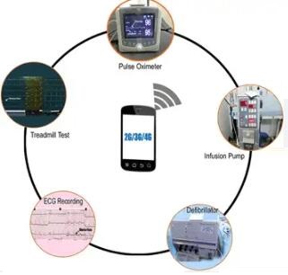
Radio frequency is measured in units called hertz (Hz), which represent the number of cycles per second when a radio wave is transmitted. One hertz equals one cycle per second; radio waves range from thousands (kilohertz) to millions (megahertz) to billions (gigahertz) of cycles per second.s the radiation from cell phones harmful? Cell phones emit radiation in the radiofrequency region of the electromagnetic spectrum. Second-, third-, and fourth-generation cell phones (2G, 3G, 4G) emit radiofrequency in the frequency range of 0.7–2.7 GHz.Today qihe smt pick and place machine sharing Complete analysis of the most practical mobile phone radio frequency terms .
- What is RF?
Answer: RF is Radio frequency, which mainly includes wireless transceivers. - What are the frequencies of mobile phones in the world today (CDMA, GSM, local telephone, PHS, analog mobile phones, etc.)?
Answer: EGSM RX: 925-960MHz, TX: 880-915MHz;
CDMA cellular (IS-95) RX: 869-894MHz, TX: 824-849MHz. - How should a novice who has been engaged in mobile RF work for a long time improve?
Answer: First of all, you should have a systematic understanding of the RF system (such as functionality), and then you can choose some chipsets and study a connectivity among them (connectivities among them). - What is the role of RF simulation software in mobile phone design and debugging?
Answer: The purpose is to give the designer some understanding of the product to be designed before implementing the design. qihe pick and place machine - What are the basic principles when designing the PCB of a mobile phone?
Answer: The basic principle is to minimize EMC. - The hardware components of mobile phones include RF/ABB/DBB/MCU/PMU. What do ABB, DBB, and PMU mean here?
Answer: ABB is Analog BaseBand,
DBB is Ditital Baseband, MCU is often included in the DBB chip.
PMU is the Power Management Unit, and some mobile phone PMU and ABB are on the same chip. In the future, these chips (RF, ABB, DBB, MCU, PMU) will be integrated into one chip to save cost and volume.
- What are the main functions of DSP and MCU? What is the difference between the two?
Answer: In fact, both MCU and DSP are processors, and there is not much difference in theory. But in the actual system, based on efficiency considerations, DSP generally handles various algorithms, such as channel codec, encryption, etc., while MCU handles signaling and communicates with most hardware peripherals (such as LCD, etc.). - What should newbies who are just starting to engage in RF front-end design pay attention to?
Answer: First of all, you can choose an RF topic, such as PLL, and learn some basic theories, and then start to design some simple circuits. Only in debugging can you gain some experience, which will help you deepen your understanding. - Recommended RF simulation software and its features?
A: Agilent ADS simulation software for RF simulation. This software supports discrete RF design and complete system design. See the Agilent website for details. - Where can I download the corresponding knowledge about the mobile phone design scheme, including several modules, the functions of each module, and the performance requirements for the hardware?
Answer: You can take a look at www.gsmworld.com and www.139130.net, which may be helpful. For information about TI’s wireless solution, you can check out wireless communications in www.ti.com.
- Why does GSM use GMSK modulation, while W-CDMA uses HPSK modulation?
Answer: Mainly due to the GSM and WCDMA standards. If you are interested, you can read some books about digital modulation to understand the pros and cons of using different digital modulation techniques. - How to solve the LCD model’s RF interference?
Answer: During the PCB design process, LCD routing can be done in a single layer. - During the mobile phone design process, among the newly added functions, the baseband chip generates noise interference to FM when transmitting data. How to solve this problem?
Answer: Check the PCB design, find the source of interference and strengthen isolation. - How to solve the RF interference problem when designing the RF transceiver part of a mobile phone?
Answer: GSM mobile phones work in TDMA mode, and RF transmission and reception are not performed at the same time. The basic principle of reducing RF interference is to strengthen matching and isolation. When designing, it should be considered that the transmitter is in a state of high-power transmission, which is more likely to cause interference than the receiver, so it is necessary to ensure the matching of the PA. In addition, the isolation of the RF front-end filter is also an important indicator. PCB boards are generally 6 or 8 layers and must have enough ground plane to reduce RF interference. - How to eliminate GSM burst interference?
Answer: During PCB wiring, the digital and radio frequency parts must be well separated, and a good ground plane must be ensured. Some power and signal lines must have effective capacitive filtering.
- How to solve RF power interference?
A: You must ensure that the RF power supply is well filtered. Separate power supplies can be used for different RF lines if necessary. - There is an RF application circuit. When the RF part is not working, the CPU and other related peripherals work normally; but when the RF starts to work, the port of the CPU that has nothing to do with RF is also disturbed by similar spikes. Please tell me, what is the reason? How to overcome such interference?
Answer: It may be that the RF part is not well isolated from the CPU part, please check the PCB layout. - What are the main considerations when choosing a mobile phone RF chip?
Answer: The following points are mainly considered when selecting an RF chip:
① RF performance, including reliability.
② High integration, requiring less peripheral components.
③ cost factor. - How to use mobile phone RF chips to reduce the number of peripheral chips?
Answer: The higher the integration level of mobile phone RF chips, the fewer peripheral components are required. - Will the radio frequency chip produce electromagnetic interference to the peripheral chips, and how should it be eliminated?
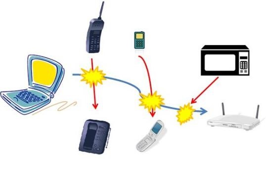
Answer: It should be said that the RF system will cause electromagnetic interference to other DBBs and ABBs, not just the RF chip. Strengthening radio frequency shielding is an effective measure.
- In a wireless communication system, should baseband time-domain equalization be performed after baseband demodulation and bit synchronization extraction, and then perform threshold judgment on the results of each bit extraction after time-domain equalization?
Answer: Yes. It needs to be equalized first, and then the threshold decision is made. - For the same transmission power, when the frequency is different, is the transmission distance of the high frequency (such as 900MHz) long, and the transmission distance of the low frequency (such as 30MHz) is short (in an open area)?
Answer: The wavelength factor should be taken into consideration. The higher the frequency, the shorter the wavelength, and the greater the transmission loss in open areas, so the transmission distance is shorter. qihe pick and place machine - Use timer 1 to generate waveforms, the program is as follows:
LDP #232
SPLK #0Ah,T1PR
SPLK #05h, T1CMPR
SPLK #0000h, T1CNT
SPLK #0042h, GPTCON
SPLK #0D542h, T1CON
Why is there no waveform output on the T1PWM/T1CMP pin?
A: You can use emulation tools to step into the code to debug this issue.
- “The bandwidth of the front-end filter of the mobile phone receiver is determined according to the bandwidth of the receiving frequency. It is necessary to ensure that the in-band signal passes through with the minimum insertion loss and is not filtered out.” Under the condition that the signal can be received effectively, the front-end filter If the filter bandwidth is relatively wide, the insertion loss of the filter will be small (I don’t know if it is the same for SAW), but the noise in the band will increase, and vice versa. Then, given the frequency range of the received signal, how should the bandwidth of the filter be considered so that the in-band signal passes through with the minimum insertion loss?
Answer: This issue should be considered from the perspective of system design, including frequency range (frequency range, sensitivity) and sensitivity (selectivity). A trade-off can be achieved between insertion loss, bandwidth, and out-of-band rejection, as long as the values chosen meet the system requirements.
- Generally speaking, PA and SWITH have the ability to suppress stray radiation, but there are certain limitations. How to add other methods to better solve it?
Answer: The accurate statement is that the matched filter of the PA has the ability to suppress spurious radiation to a certain extent. In addition, a good front-end filter can be selected to enhance out-of-band suppression. qihe pick and place machine - How to choose RF LDO?
Answer: When selecting an LDO, you should consider some of its own characteristics, such as driving current, output noise, and ripple rejection. - What methods can be used to reduce the power consumption of the radio frequency system during standby?
Answer: You can turn off the radio frequency system while listening to network paging information on your mobile phone. - The TRF6151 chip launched by TI uses direct frequency conversion technology. Will it cause other problems?
Answer: The TRF6151 chip launched by TI is a single-chip GSM tranceiver, using a zero-IF receiver structure. Direct conversion technology is now very mature, there are no technical problems, and it is still the current mainstream solution - The TRF6151 chip launched by TI uses direct frequency conversion technology. Will it cause other problems?
Answer: The TRF6151 chip launched by TI is a single-chip GSM tranceiver, using a zero-IF receiver structure. Direct frequency conversion technology is now very mature, has no technical problems, and is still the current mainstream solution. - What is the requirement for phase noise at 1k offset, 10kHz offset, and 100kHz offset for GSM handset? What conditions need to be met when the phase noise of GSM mobile phones is 1k, 10kHz and 100kHz?
Answer: For GSM handset RX it has several architectures to implement: Superheterodyne,near zero-IF,zero-IF,different architecture may have different
LOs requirement and frequency plan,also it’s related to the design of filters.
For GSM mobile phone RX, it is necessary to achieve: superheterodyne close to zero intermediate frequency (zero-IF). The zero-IF of different architectures is different. Los requirements and frequency plan, which are related to the design of the filter. - The static sound quality of the receiver is very good when the receiving sensitivity is high, but not good when it is moving. What may be the reason?
Answer: It may be the effect of fading.
- In TI’s solution, does the DSP software share the same operating system with the MCU software?
Answer: In TI’s solution, even in all solutions, DSP software cannot share an operating system with MCU software. Although they are integrated on one chip, they are independent modules, equivalent to two independent processors. - How to reduce spectrum_switch?
Answer: If it is a closed-loop power control, it must be noted that the PA output power detection circuit can meet the GSM dynamic range. - The switching frequency of mobile phones is very fast. In the past, the mobile phones we used usually used two phase-locked loops to lock the frequency. Now in the single-chip system, only one phase-locked loop is used, using N fractional frequency locking technology. What is the general time control? How many seconds is appropriate?
Answer: The locking time depends on the specific application, less than 250us can meet the requirements of gprs class 12. - What problems should be paid attention to during the early and late pcb debugging?
A: Need to adjust the power control of burst ramp up and ramp down. - Can TI provide the source code of MMI?
Answer: In general, TI provides the MMI source code together with the source code of some drivers (LCD, etc.) to users. All source codes including MMI, protocol stack and layer1 source codes will be provided based on business relationship. - How to solve the second resonance or multiple resonances of the high frequency LC oscillator circuit?
Answer: You can improve the frequency selectivity of the oscillator feedback network, or use an input matching circuit to attenuate harmonics.
Attachment: Relevant original English answers:
You can improve the frequency selectivity of oscillator feedback network or take advantage of the output matching circuitry to attenuate the harmonics. - The quality of RF port matching directly affects the signal quality of the RF link. How can these matching circuits be debugged the fastest and best?
Answer: Step one: You can use a network analyzer to measure the actual S parameters based on the circuit board design and input them into the RF simulation SW to obtain the initial matching network. Step 2: Based on the simulation results of the matching network, some further optimization work can be done on the board. qihe pick and place machine
Best seller SMT Machine :Qihe smt line products
-
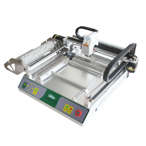
TVM925 SMT pick and place machine 4 head 38 feeders slots assembly of electronic components
-
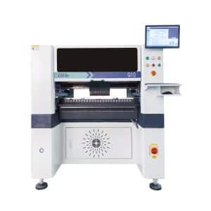
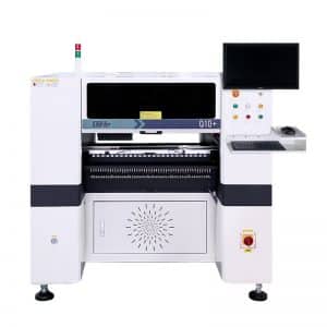
Q10 SMT Automatic pick and place machine 10 Heads 100 Slots High Precision and High Efficiency SMT/LED Assembly
-
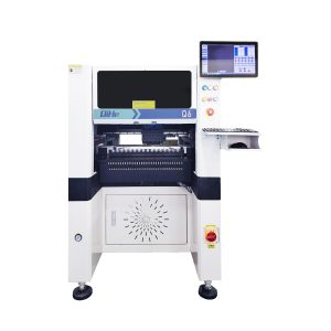
Q6 SMT pick and place machine 6heads 50slots With PCB Rail Servo Pick&Place Machine
-
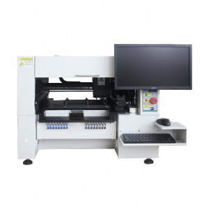
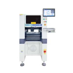
Q4 SMT pick and place machine 4heads 50slots With PCB Rail Servo Pick&Place Machine
-
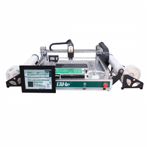
TVM802B Plus SMT pick and place machine 2heads 58slots desktop pick&place deluxe edition
-
QM10 SMT pick and place machine 10heads 80slots Fully Automatic Chip mounter SMT Assembly
-
TVM802BX SMT pick and place machine 2heads 46slots desktop pnp mounter deluxe edition
-
QL41 SMT pick and place machine 4heads 8slots LED for 1.2meters led strip pick&place machine
-
Q8 SMT pick and place machine 8heads 80slots Fully Automatic Chip mounter SMT Assembly
What is SMT in engineering?
Surface mount technology is a part of the electronic assembly that deals with the mounting of electronic components to the surface of a PCB. Electronic components mounted this way are called surface-mounted devices (SMD). SMT was developed to minimize manufacturing costs while making efficient use of board space.Qihe SMT company develops and produces all kinds of SMT equipment suitable for world wide market, including pnp machine,reflow oven,stencil printer,pcb handling machines,and other products.
Small desktop pick and place machine TVM802A,TVM802B,TVM802AX,TVM802BX series suitable for beginners, for hobbiest or low vol usag.
Advanced level 4-head LED strip placement QL41 led machines and with rail universal series TVM925S,TVM926S,
Fully automatic 6-10-head placement QM61,QM62,QM81,QM10,machines, which are suitable for high volume mass production in factories.
Know more about us https://www.qhsmt.com/about-qihe-smt-equipment/
Follow us on social media https://www.facebook.com/Qihesmt/
What is SMT in programming?
Offline Automated Programming vs Inline SMT Programming
Qihe pick and place machine can be programmed directly on the SMT equipment .
Or Coordinates can also be imported csv file through programming software.
Currently supported software such as protel,DXP,Altium Designer,Pads,Candes,proteus,DXP.
Inline SMT programming is a solution to consider for narrow segments of device programming requiring short programming times, with medium to high volume, for just one device type.
WHAT IS SMT pick and place machine?
SMT (Surface Mounted Technology) is a comprehensive system engineering technology, which covers substrates, design, equipment, components, assembly processes, production accessories and management. When it comes to SMT pick and place machines, the automatic SMT production line requires automatic loading and unloading machine, automatic solder paste printing machine, placement machine, reflow soldering machine, AOI inspection equipment, conveyor,connecting table, etc. For these SMT assembly line equipment, Qihe SMT can offer you machines in prototype SMT line, small SMT production line, mass production SMT line at low SMT line cost. Contact us now if you are interested.
WHAT IS SMT ASSEMBLY LINE?
With the development of technology, future electronic products will be lighter, smaller and thinner. pick and place machine Traditional assembly technology can no longer meet the requirements of high-precision and high-density assembly. A new type of PCB assembly technology-SMT (Surface Mount Technology) has emerged. SMT Assembly is the use of automated machines to assemble electronic components on the surface of the circuit board. Its density, high speed, standardization and other characteristics occupies an absolute advantage in the field of circuit assembly technology. In addition, SMT assembly has a wide range of uses.
https://www.qhsmt.com/fully-automatic-smt-pick-and-place-machine-line/

