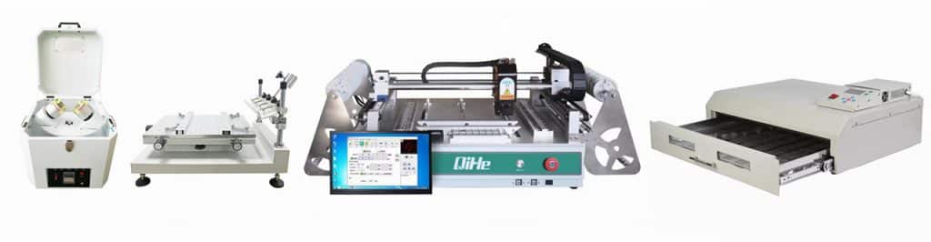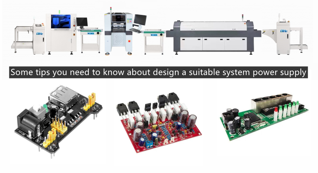
For an electronic system nowadays, the design of the power supply part is becoming increasingly important. I would like to discuss with you some of my own experiences on power supply design, in order to introduce ideas and make progress in power supply design.Today qihe smt pick and place machine sharing some tips you need to know about design a suitable system power supply.
Q1: How to evaluate the power requirements of a system
Answer: For an actual electronic system, it is necessary to carefully analyze its power requirements. Not only do we care about the input voltage, output voltage, and current, but we also need to carefully consider the overall power consumption, the efficiency of the power supply implementation, the transient response ability of the power supply to load changes, the tolerance range of key components to power fluctuations, the corresponding allowable power ripple, and heat dissipation issues. Power consumption and efficiency are closely related. With higher efficiency, the total power consumption will be reduced under the same load power consumption, which is very beneficial for the power budget of the entire system. Compared to LDO and switching power supplies, the efficiency of switching power supplies is higher. At the same time, evaluating efficiency not only depends on the efficiency of the power circuit at full load, but also on the efficiency level at light load.
As for the transient response capability of the load, there are strict requirements for some high-performance CPU applications, because when the CPU suddenly starts running heavy tasks, the required startup current is very high. If the power circuit response speed is not enough, it will cause the instantaneous voltage to drop too much or too low, causing CPU operation errors.
Generally speaking, the actual value of the required power supply is usually+-5% of the nominal value, so the allowable power ripple can be calculated based on this, and of course, a margin should be reserved.
The issue of heat dissipation is important for those high current power supplies and LDOs, and calculation can also be used to evaluate their suitability.
Q2: How to Choose a Suitable Power Supply to Implement a Circuit
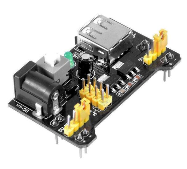
Answer: Based on the specific technical indicators obtained from analyzing the system requirements, a suitable power supply can be selected to implement the circuit. Generally, for the weak current part, it includes LDO (linear power converter), switch power capacitor step-down converter, and switch power inductor capacitor converter. In contrast, LDO design is the easiest to implement, with small output ripple, but its drawbacks include low efficiency, high heat generation, and a relatively small current supply compared to switching power supplies. The design of the switch power supply circuit is flexible and efficient, but it has large ripple, complex implementation, and cumbersome debugging.
Q3: How to Select Appropriate Components and Parameters for Switching Power Supply Circuits
Answer: Many engineers who have not used the design of switching power supplies may develop a certain level of fear towards it, such as concerns about interference issues with switching power supplies, PCB layout issues, and the selection of component parameters and types. In fact, as long as you understand, using a switching power supply design is still very convenient.
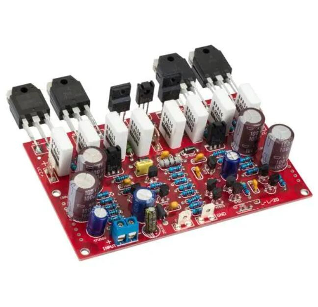
A switching power supply generally includes two parts: a switching power supply controller and an output. Some controllers integrate MOSFETs into the chip, making it easier to use and simplifying PCB design. However, the flexibility of the design is reduced.
The switch controller is basically a closed-loop feedback control system, so there is usually a sampling circuit for feedback output voltage and a control circuit for the feedback loop. Therefore, the design of this part is to ensure accurate sampling circuits and control feedback depth, as if the feedback loop response is too slow, it will have a significant impact on the transient response ability.
The design of the output part includes output capacitors, output inductors, MOSFETs, and so on. These choices are basically to meet a balance between performance and cost. For example, a high switching frequency can use a small inductance value (meaning small packaging and cheap cost), but a high switching frequency will increase interference and switch losses on MOSFETs, thereby reducing efficiency. The result of using a low switching frequency is the opposite.
For ESR of output capacitors and Rds of MOSFETs_ The selection of on parameters is also crucial. A small ESR can reduce output ripple, but the cost of capacitors will increase. Good capacitors will be expensive. Attention should also be paid to the driving ability of the switching power supply controller, as excessive MOSFETs cannot be well driven.
Generally speaking, the supplier of switching power supply controllers will provide specific calculation formulas and usage plans for engineers to learn from.
Q4: How to debug switch power supply circuits
Answer: There are some experiences that can be shared with everyone
1: The output of the power circuit is connected to the board through a low resistance value high-power resistor, so that the power circuit can be debugged first without soldering the resistor, avoiding the influence of subsequent circuits.
2: Generally speaking, a switch controller is a closed-loop system. If the output deteriorates beyond the range that can be controlled by the closed-loop, the switch power supply will not work properly. Therefore, this situation requires careful inspection of the feedback and sampling circuits. Especially if an output capacitor with a large ESR value is used, it will generate a lot of power ripple, which will also affect the operation of the switching power supply.pick and place machine
Discussion on grounding technology
Q1: Why grounding?
Answer: The introduction of grounding technology was initially a protective measure taken to prevent electrical or electronic equipment from being struck by lightning, with the aim of introducing the lightning current generated by lightning through lightning rods to the ground, thereby protecting buildings. At the same time, grounding is also an effective means of protecting personal safety. When the phase line (such as poor wire insulation, line aging, etc.) and the equipment casing come into contact due to certain reasons, there will be dangerous voltage generated on the equipment casing, and the generated fault current will flow through the PE line to the ground, thus playing a protective role. With the development of electronic communication and other digital fields, considering only lightning protection and safety in grounding systems is far from meeting the requirements. For example, in communication systems, the interconnection of signals between a large number of devices requires each device to have a reference ‘ground’ as the signal reference ground. Moreover, with the complexity of electronic devices, signal frequencies are increasing. Therefore, in grounding design, electromagnetic compatibility issues such as signal interference must be given special attention. Otherwise, improper grounding will seriously affect the reliability and stability of system operation. Recently, the concept of “ground” has also been introduced in the signal backflow technology of high-speed signals.pick and place machine
Q2: Definition of Grounding
Answer: In modern grounding concepts, for line engineers, the meaning of this term is usually ‘reference point of line voltage’; For system designers, it is often a cabinet or rack; For electrical engineers, it means green safety ground wire or connecting to the ground. A more general definition is’ grounding is the low impedance channel through which current returns to its source ‘. The requirements for attention are “low impedance” and “path”.
Q3: Common grounding symbols
Answer: PE, PGND, FG – protective ground or casing; BGND or DC RETURN – DC 48V (+24V) power supply (battery) return current; GND – workplace; DGND – Digital Ground; AGND – simulated ground; LGND – Lightning Protection Ground
Q4: Suitable grounding method
Answer: There are various grounding methods, including single point grounding, multi-point grounding, and mixed types of grounding. And single point grounding can be divided into series single point grounding and parallel single point grounding. Generally speaking, single point grounding is used for simple circuits, grounding differentiation between different functional modules, and low-frequency (f<1MHz) electronic circuits. When designing high-frequency (f>10MHz) circuits, it is necessary to use multi-point grounding or multi-layer boards (complete ground plane layer).
Q5: Introduction to Signal Reflow and Cross Segmentation
Answer: For an electronic signal, it needs to find a path for the lowest impedance current to return to ground, so how to handle this signal return becomes very crucial.
Firstly, according to the formula, it can be known that the radiation intensity is proportional to the circuit area. This means that the longer the path that the reflux needs to take, the larger the loop formed, and the greater its interference with external radiation. Therefore, when laying out PCB boards, it is necessary to minimize the area product of the power circuit and signal circuit as much as possible.pick and place machine
Secondly, for a high-speed signal, providing good signal return can ensure its signal quality. This is because the characteristic impedance of the PCB transmission line is generally calculated based on the ground layer (or power supply layer). If there is a continuous ground plane near the high-speed line, the impedance of the line can remain continuous. If there is no ground reference near a section of the line, the impedance will change, Discontinuous impedance can affect the integrity of the signal. So, when wiring, it is necessary to allocate the high-speed line to a layer close to the ground plane, or to walk one or two ground wires next to the high-speed line, to serve as a shield and provide nearby backflow.
Thirdly, why do we try not to split across power sources when wiring? This is also because after the signal crosses different power layers, its return path will be long and easy to be interfered with. Of course, it is not a strict requirement to not cross the power supply division. It is acceptable for low-speed signals because the interference generated can be ignored compared to the signal. For high-speed signals, it is necessary to carefully check and try not to cross them. You can adjust the wiring of the power supply section. (This is for the situation where multiple power supplies are provided to multi-layer boards.)
Q6: Why should analog ground and digital ground be separated, and how should they be separated?
Answer: Both analog and digital signals need to return to the ground because digital signals change rapidly, causing significant noise on the digital ground. Analog signals require a clean ground reference for operation. If analog and digital are mixed together, noise will affect the analog signal.
Generally speaking, analog ground and digital ground should be processed separately, and then connected together through thin wiring or single point connection. The overall idea is to try to block the noise from digital ground to analog ground as much as possible. Of course, this is not a very strict requirement that the analog ground and digital ground must be separated. If the digital ground near the analog part is still very clean, it can be combined together.
Q7: How is the signal on the board grounded?
Answer: For general devices, grounding nearby is the best option. After adopting a multi-layer board design with a complete ground plane, grounding for general signals is very easy. The basic principle is to ensure continuity of wiring and reduce the number of vias; Near ground level or power level, etc.pick and place machine
Q8: How to ground the interface components of a single board?
Answer: Some boards may have external input and output interfaces, such as serial connectors, network RJ45 connectors, etc. If their grounding design is not good, it will also affect normal operation, such as network port interconnection errors, packet loss, etc., and will become an external electromagnetic interference source, sending out the noise inside the board. Generally speaking, a separate interface ground will be separated and connected to the signal ground using fine wiring, which can be connected in series with a resistance of 0 ohms or a small resistance value. Thin wiring can be used to block signal ground noise from passing to the interface ground. Similarly, careful consideration should be given to the filtering of interface ground and interface power supply.
Q9: How is the shielding layer of a cable with a shielding layer grounded?
Answer: The shielding layer of the shielded cable should be connected to the interface ground of the single board instead of the signal ground. This is because there are various noises on the signal ground. If the shielding layer is connected to the signal ground, the noise voltage will drive the common mode current to interfere outward along the shielding layer. Therefore, poorly designed cables are generally the largest source of electromagnetic interference output. Of course, the premise is that the interface should also be very clean.
Read more: Some tips you need to know about design a suitable system power supplyBest seller SMT Machine :Qihe smt line products
-
 SMT semi-automatic pick and place machine with Dispenser
 -
TVM925 SMT pick and place machine 4 head 38 feeders slots assembly of electronic components
-
Q10 SMT Automatic pick and place machine 10 Heads 100 Slots High Precision and High Efficiency SMT/LED Assembly
-
Q6 SMT pick and place machine 6heads 50slots With PCB Rail Servo Pick&Place Machine
-
Q4 SMT pick and place machine 4heads 50slots With PCB Rail Servo Pick&Place Machine
-
TVM802B Plus SMT pick and place machine 2heads 58slots desktop pick&place deluxe edition
-
QM10 SMT pick and place machine 10heads 80slots Fully Automatic Chip mounter SMT Assembly
-
TVM802BX SMT pick and place machine 2heads 46slots desktop pnp mounter deluxe edition
-
QL41 SMT pick and place machine 4heads 8slots LED for 1.2meters led strip pick&place machine


What is SMT in engineering?
Surface mount technology is a part of the electronic assembly that deals with the mounting of electronic components to the surface of a PCB. Electronic components mounted this way are called surface-mounted devices (SMD). SMT was developed to minimize manufacturing costs while making efficient use of board space.Qihe SMT company develops and produces all kinds of SMT equipment suitable for world wide market, including pnp machine,reflow oven,stencil printer,pcb handling machines,and other products.
Small desktop pick and place machine TVM802A,TVM802B,TVM802AX,TVM802BX series suitable for beginners, for hobbiest or low vol usag.
Advanced level 4-head LED strip placement QL41 led machines and with rail universal series Q4,TVM925S,TVM926S,pick and place
Fully automatic 6-10-head placement QM61,QM62,QM81,QM10,machines, which are suitable for high volume mass production in factories.
Know more about us https://www.qhsmt.com/about-qihe-smt-equipment/
Follow us on social media https://www.facebook.com/Qihesmt/
What is SMT in programming?
Offline Automated Programming vs Inline SMT Programming
Qihe pick and place machine can be programmed directly on the SMT equipment .
Or Coordinates can also be imported csv file through programming software.
Currently supported software such as protel,DXP,Altium Designer,Pads,Candes,proteus,DXP.
Inline SMT programming is a solution to consider for narrow segments of device programming requiring short programming times, with medium to high volume, for just one device type.pick and place machine
WHAT IS SMT pick and place machine?
SMT (Surface Mounted Technology) is a comprehensive system engineering technology, which covers substrates, design, equipment, components, assembly processes, production accessories and management. When it comes to SMT pick and place machines, the automatic SMT production line requires automatic loading and unloading machine, automatic solder paste printing machine, placement machine, reflow soldering machine, AOI inspection equipment, conveyor,connecting table, etc. For these SMT assembly line equipment, Qihe SMT can offer you machines in prototype SMT line, small SMT production line, mass production SMT line at low SMT line cost. Contact us now if you are interested.pick and place
WHAT IS SMT ASSEMBLY LINE?
With the development of technology, future electronic products will be lighter, smaller and thinner. Traditional assembly technology can no longer meet the requirements of high-precision and high-density assembly. A new type of PCB assembly technology-SMT (Surface Mount Technology) has emerged. SMT Assembly is the use of automated machines to assemble electronic components on the surface of the circuit board. Its density, high speed, standardization and other characteristics occupies an absolute advantage in the field of circuit assembly technology. In addition, SMT assembly has a wide range of uses.
https://www.qhsmt.com/fully-automatic-smt-pick-and-place-machine-line/