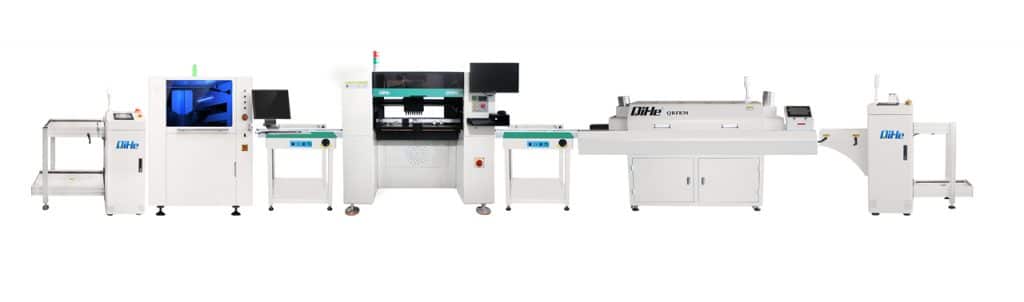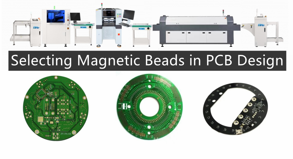
Whether to use SMD magnetic beads or SMD inductors in PCB design mainly depends on the application scenario. Chip inductors are required in resonant circuits. When it is necessary to eliminate unnecessary EMI noise, using SMD magnetic beads is the best choice.Today qihe smt pick and place machine sharing some tips for Selecting Magnetic Beads in PCB Design.
The unit of magnetic beads is ohms, not Hunter, which requires special attention. Because the unit of magnetic beads is nominal based on the impedance it generates at a certain frequency, and the unit of impedance is also ohms. The DATASHEET of magnetic beads usually provides characteristic curves of frequency and impedance, usually based on 100MHz, such as 1000R100MHz, which means that the impedance of magnetic beads is equivalent to 600 ohms at 100MHz.
A regular filter is composed of lossless reactance components, and its function in the circuit is to reflect the stopband frequency back to the signal source, so this type of filter is also called a reflection filter. When the reflection filter does not match the impedance of the signal source, a portion of energy will be reflected back to the signal source, causing an increase in interference level. To solve this problem, a ferrite magnetic ring or bead sleeve can be used on the inlet line of the filter, utilizing the eddy current loss of the magnetic ring or bead on the high-frequency signal to convert the high-frequency component into heat loss. Therefore, magnetic rings and beads actually absorb high-frequency components, so they are sometimes referred to as absorption filters.
Different ferrite suppression elements have different optimal suppression frequency ranges. Usually, the higher the magnetic permeability, the lower the frequency of suppression. In addition, the larger the volume of ferrite, the better the inhibitory effect. Some online studies have found that when the volume is constant, long and thin shapes have better inhibitory effects than short and thick shapes, and the smaller the inner diameter, the better the inhibitory effect. However, in the case of DC or AC bias currents, there is also a problem of ferrite saturation. The larger the cross-sectional area of the suppression element, the less likely it is to be saturated, and the greater the allowable bias current. When EMI absorbs magnetic rings/beads to suppress differential mode interference, its current value is directly proportional to its volume, and the imbalance between the two causes saturation, which reduces component performance; When suppressing common mode interference, the two wires (positive and negative) of the power supply are simultaneously passed through a magnetic ring, and the effective signal is a differential mode signal. EMI absorption of the magnetic ring/bead has no effect on it, while for common mode signals, it will show a large inductance. Another good method for using magnetic rings is to repeatedly wind the wires passing through the magnetic ring several times to increase the inductance. According to its principle of suppressing electromagnetic interference, its inhibitory effect can be reasonably used.
The ferrite suppression element should be installed near the interference source. For input/output circuits, they should be located as close as possible to the inlet and outlet of the shielding shell. For the absorption filter composed of ferrite magnetic rings and beads, in addition to selecting high permeability lossy materials, attention should also be paid to its application occasions. Their resistance to high-frequency components in the circuit is approximately ten to several hundred Ω, so their role in high impedance circuits is not significant. On the contrary, their use in low impedance circuits (such as power distribution, power supply, or RF circuits) will be very effective.
Due to its ability to attenuate higher frequencies while allowing lower frequencies to pass almost unobstructed, ferrite has been widely used in EMI control. Magnetic rings/beads used for EMI absorption can be made into various shapes and widely used in various occasions. If on a PCB board, it can be added to DC/DC modules, data cables, power cables, etc. It absorbs high-frequency interference signals on the line where it is located, but it does not generate new zeros and poles in the system and does not disrupt the stability of the system. It can be used in conjunction with a power filter to effectively supplement the shortcomings of the high-frequency performance of the filter and improve the filtering characteristics in the system.
Magnetic beads are specifically designed to suppress high-frequency noise and peak interference on signal and power lines, and also have the ability to absorb electrostatic pulses.
Magnetic beads are used to absorb ultra-high frequency signals, such as some RF circuits, PLLs, oscillation circuits, and circuits containing ultra-high frequency memory (DDRSDRAM, RAMBUS, etc.) that require magnetic beads to be added to the power input. Inductors are energy storage components used in LC oscillation circuits, medium and low frequency filtering circuits, and their application frequency range rarely exceeds 50MHz.
The main function of magnetic beads is to eliminate RF noise present in transmission line structures (circuits). RF energy is the AC sine wave component superimposed on the DC transmission level, and the DC component is the useful signal required. However, RF energy is useless electromagnetic interference transmitted and radiated along the line (EMI). To eliminate these unnecessary signal energy, a patch magnetic bead is used to act as a high-frequency resistor (attenuator), which allows DC signals to pass through while filtering out AC signals. Usually, high-frequency signals are above 30MHz, however, low-frequency signals can also be affected by SMD magnetic beads.
SMD magnetic beads are composed of soft ferrite materials, forming a high volume resistivity monolith structure. The eddy current loss is inversely proportional to the resistivity of ferrite materials. The eddy current loss is proportional to the square of the signal frequency.
The benefits of using SMD magnetic beads: miniaturization and lightweight have high impedance in the frequency range of RF noise, eliminating electromagnetic interference in transmission lines. Closed magnetic circuit structure, better eliminating signal string winding. Excellent magnetic shielding structure. Reduce the DC resistance to avoid excessive attenuation of useful signals. Significant high-frequency and impedance characteristics (better elimination of RF energy). Eliminating parasitic oscillations in high-frequency amplification circuits. Effective operation in the frequency range of several MHz to several hundred MHz.
Several suggestions for selecting magnetic beads correctly in PCB design:
1、 What is the frequency range of unnecessary signals;
2、 Who is the noise source;
3、 Is there space to place magnetic beads on the PCB board;
4、 How much noise attenuation is required;
5、 What are the environmental conditions (temperature, DC voltage, structural strength);
6、 What is the circuit and load impedance;
The first three can be determined by observing the impedance frequency curve provided by the manufacturer. In the impedance curve, all three curves are very important, namely resistance, inductance, and total impedance. The total impedance is described by ZR22 π fL() 2+:=fL. Through this curve, select the magnetic bead model that has the maximum impedance within the frequency range of desired noise attenuation and minimizes signal attenuation at low frequencies and DC. Under excessive DC voltage, the impedance characteristics of SMD magnetic beads will be affected. In addition, if the operating temperature rises too high or the external magnetic field is too large, the impedance of the magnetic beads will be adversely affected. You can also choose at the Shenzhen Electronics Exhibition. The reason for using SMD magnetic beads and SMD inductors: Whether to use SMD magnetic beads or SMD inductors mainly depends on the application. Chip inductors are required in resonant circuits. When it is necessary to eliminate unnecessary EMI noise, using SMD magnetic beads is the best choice.
Application scenarios for SMD magnetic beads and SMD inductors:
Chip inductance: Radio frequency (RF) and wireless communication, information technology equipment, radar detectors, automobiles, cellular phones, pagers, audio devices, PDAs (personal digital assistants), wireless remote control systems, and low-voltage power supply modules.
Chip magnetic beads: filtering between clock generation circuits, analog and digital circuits, I/O input/output internal connectors (such as serial ports, parallel ports, keyboards, mice, long-distance telecommunications, local area networks), radio frequency (RF) circuits, and logic devices that are susceptible to interference, filtering out high-frequency conducted interference in power supply circuits, and suppressing EMI noise in computers, video recorders (VCRS), television systems, and smartphones.
Read more: Tips for Selecting Magnetic Beads in PCB DesignBest seller SMT Machine :Qihe smt line products
-
 SMT semi-automatic pick and place machine with Dispenser
 -
TVM925 SMT pick and place machine 4 head 38 feeders slots assembly of electronic components
-
Q10 SMT Automatic pick and place machine 10 Heads 100 Slots High Precision and High Efficiency SMT/LED Assembly
-
Q6 SMT pick and place machine 6heads 50slots With PCB Rail Servo Pick&Place Machine
-
Q4 SMT pick and place machine 4heads 50slots With PCB Rail Servo Pick&Place Machine
-
TVM802B Plus SMT pick and place machine 2heads 58slots desktop pick&place deluxe edition
-
QM10 SMT pick and place machine 10heads 80slots Fully Automatic Chip mounter SMT Assembly
-
TVM802BX SMT pick and place machine 2heads 46slots desktop pnp mounter deluxe edition
-
QL41 SMT pick and place machine 4heads 8slots LED for 1.2meters led strip pick&place machine


What is SMT in engineering?
Surface mount technology is a part of the electronic assembly that deals with the mounting of electronic components to the surface of a PCB. Electronic components mounted this way are called surface-mounted devices (SMD). SMT was developed to minimize manufacturing costs while making efficient use of board space.Qihe SMT company develops and produces all kinds of SMT equipment suitable for world wide market, including pnp machine,reflow oven,stencil printer,pcb handling machines,and other products.
Small desktop pick and place machine TVM802A,TVM802B,TVM802AX,TVM802BX series suitable for beginners, for hobbiest or low vol usag.
Advanced level 4-head LED strip placement QL41 led machines and with rail universal series Q4,TVM925S,TVM926S,pick and place
Fully automatic 6-10-head placement QM61,QM62,QM81,QM10,machines, which are suitable for high volume mass production in factories.
Know more about us https://www.qhsmt.com/about-qihe-smt-equipment/
Follow us on social media https://www.facebook.com/Qihesmt/
What is SMT in programming?
Offline Automated Programming vs Inline SMT Programming
Qihe pick and place machine can be programmed directly on the SMT equipment .
Or Coordinates can also be imported csv file through programming software.
Currently supported software such as protel,DXP,Altium Designer,Pads,Candes,proteus,DXP.
Inline SMT programming is a solution to consider for narrow segments of device programming requiring short programming times, with medium to high volume, for just one device type.
WHAT IS SMT pick and place machine?
SMT (Surface Mounted Technology) is a comprehensive system engineering technology, which covers substrates, design, equipment, components, assembly processes, production accessories and management. When it comes to SMT pick and place machines, the automatic SMT production line requires automatic loading and unloading machine, automatic solder paste printing machine, placement machine, reflow soldering machine, AOI inspection equipment, conveyor,connecting table, etc. For these SMT assembly line equipment, Qihe SMT can offer you machines in prototype SMT line, small SMT production line, mass production SMT line at low SMT line cost. Contact us now if you are interested.pick and place
WHAT IS SMT ASSEMBLY LINE?
With the development of technology, future electronic products will be lighter, smaller and thinner. Traditional assembly technology can no longer meet the requirements of high-precision and high-density assembly. A new type of PCB assembly technology-SMT (Surface Mount Technology) has emerged. SMT Assembly is the use of automated machines to assemble electronic components on the surface of the circuit board. Its density, high speed, standardization and other characteristics occupies an absolute advantage in the field of circuit assembly technology. In addition, SMT assembly has a wide range of uses.
https://www.qhsmt.com/fully-automatic-smt-pick-and-place-machine-line/