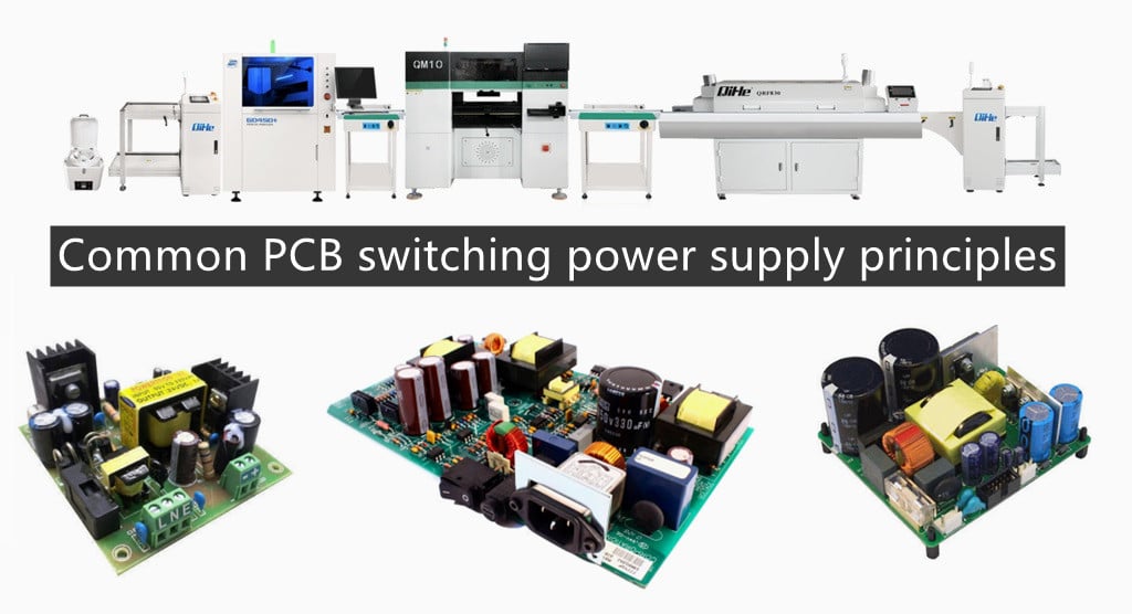
As the world attaches great importance to energy issues, the energy consumption problem of electronic products will become more and more prominent. Today qihe smt pick and place machine sharing some common PCB switching power supply principles . How to reduce their standby power consumption and improve power supply efficiency has become an urgent problem to be solved. Although the traditional linear regulated power supply has a simple circuit structure and reliable operation, it has shortcomings such as low efficiency (only 40% -50%), large volume, large consumption of copper and iron, high operating temperature, and small adjustment range. In order to improve efficiency, people have developed a switching regulated power supply, which has an efficiency of more than 85% and a wide voltage stabilizing range. In addition, it also has the characteristics of high voltage stabilization accuracy and does not use a power transformer. It is a kind of An ideal regulated power supply. Because of this, switching power supplies have been widely used in various electronic equipment. This article explains the working principles of various switching power supplies.
Basic working principle of switching power supply
The switching control mode of the regulated power supply is divided into two types: the width-adjusting type and the frequency-modulating type. In practical applications, the width-adjusting type is used more often. Among the switching power supply integrated circuits currently developed and used, the vast majority are also Pulse width modulation type. Therefore, the following mainly introduces the width-adjustable switching regulated power supply.The basic principle of the adjustable-width switching regulated power supply can be seen in the figure below.
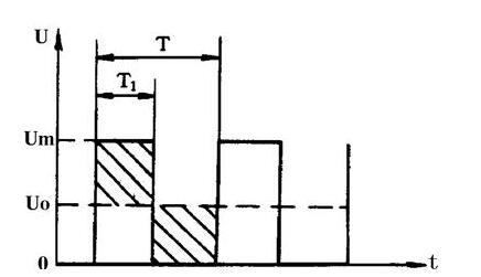
For unipolar rectangular pulses, the DC average voltage Uo depends on the width of the rectangular pulse. The wider the pulse, the higher the DC average voltage value. DC average voltage U. It can be calculated by the formula,
That is Uo=Um×T1/T
In the formula, Um is the maximum voltage value of the rectangular pulse; T is the rectangular pulse period; T1 is the rectangular pulse width.
It can be seen from the above formula that when Um and T remain unchanged, the DC average voltage Uo will be proportional to the pulse width T1. In this way, as long as we try to narrow the pulse width as the output voltage of the regulated power supply increases, we can achieve the purpose of voltage stabilization.
Principle circuit of switching power supply
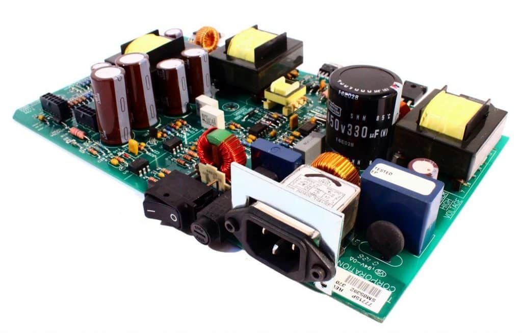
After the AC voltage is rectified and filtered by the rectifier circuit and the filter circuit, it becomes a DC voltage containing a certain pulsating component. This voltage enters the high-frequency converter and is converted into a square wave of the required voltage value. Finally, this square wave voltage is rectified. filtered to the required DC voltage.
The control circuit is a pulse width modulator, which is mainly composed of sampler, comparator, oscillator, pulse width modulation and reference voltage circuits. This part of the circuit has been integrated and made into various integrated circuits for switching power supplies. The control circuit is used to adjust the switching time ratio of high-frequency switching elements to achieve the purpose of stabilizing the output voltage.
Single-ended flyback switching power supply
The typical circuit of a single-ended flyback switching power supply is shown in Figure . The so-called single-ended in the circuit means that the magnetic core of the high-frequency converter only works on one side of the hysteresis loop. The so-called flyback means that when the switch tube VT1 is turned on, the induced voltage of the primary winding of the high-frequency transformer T is positive up and negative down, and the rectifier diode VD1 is in a cut-off state, storing energy in the primary winding. When the switch VT1 is turned off, the energy stored in the primary winding of the transformer T is output to the load through the secondary winding and VD1 rectification and capacitor C filtering.
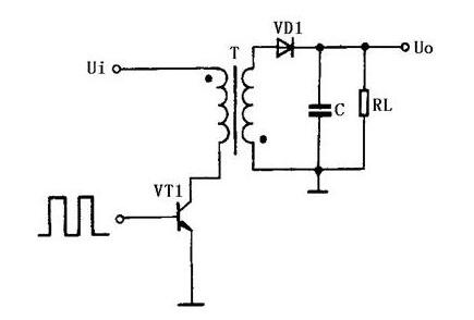
The single-ended flyback switching power supply is the lowest-cost power supply circuit with an output power of 20-100W. It can output different voltages at the same time and has a good voltage regulation rate. The only disadvantage is that the output ripple voltage is large and the external characteristics are poor, so it is suitable for relatively fixed loads.
The maximum reverse voltage that the switching tube VT1 used in the single-ended flyback switching power supply can withstand is twice the operating voltage of the circuit, and the operating frequency is between 20-200kHz.
Single-ended forward switching power supply
The typical circuit of a single-ended forward switching power supply is shown in Figure . This circuit is similar in form to a single-ended flyback circuit, but operates differently. When the switching tube VT1 is turned on, VD2 is also turned on. At this time, the power grid transmits energy to the load, and the filter inductor L stores energy; when the switching tube VT1 is turned off, the inductor L continues to release energy to the load through the freewheeling diode VD3.
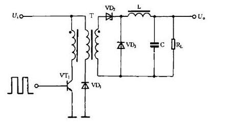
There is also a clamp coil and diode VD2 in the circuit, which can limit the maximum voltage of the switch VT1 to twice the power supply voltage. In order to meet the core reset condition, that is, the magnetic flux establishment and reset times should be equal, so the duty cycle of the pulse in the circuit cannot be greater than 50%. Since this circuit transmits energy to the load through the transformer when the switch VT1 is turned on, the output power range is large and can output 50-200 W power. The transformer used in the circuit is complex in structure and large in size. For this reason, this type of circuit has few practical applications.
Self-excited switching power supply
The typical circuit of a self-excited switching regulated power supply is shown in Figure . This is a switching power supply composed of an intermittent oscillation circuit, and it is also one of the basic power supplies currently widely used.
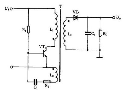
When the power supply is connected, R1 provides a starting current to the switching tube VT1, causing VT1 to begin to conduct, and its collector current Ic increases linearly in L1, and a positive feedback voltage is induced in L2 that makes the base of VT1 extremely positive and the emitter extremely negative. , causing VT1 to saturate quickly. At the same time, the induced voltage charges C1. As the charging voltage of C1 increases, the base potential of VT1 gradually becomes lower, causing VT1 to exit the saturation zone, and Ic begins to decrease.
Induced in L2, the base of VT1 is negative and the emitter is extremely negative. The positive voltage causes VT1 to cut off quickly. At this time, the diode VD1 is turned on, and the energy stored in the primary winding of the high-frequency transformer T is released to the load. When VT1 is cut off, there is no induced voltage in L2, and the DC power supply input voltage reversely charges C1 through R1, gradually increasing the base potential of VT1, causing it to re-conduct, flip again and reach saturation, and the circuit will continue to oscillate like this. . Here, just like a single-ended flyback switching power supply, the secondary winding of the transformer T outputs the required voltage to the load.
The switching tube in the self-excited switching power supply plays the dual roles of switching and oscillation, and the control circuit is also omitted. In the circuit, since the load is located on the secondary side of the transformer and works in a flyback state, it has the advantage that the input and output are isolated from each other. This circuit is not only suitable for high-power power supplies, but also for low-power power supplies.
Push-pull switching power supply
The typical circuit of push-pull switching power supply is shown in Figure 6. It is a double-ended conversion circuit, and the magnetic core of the high-frequency transformer works on both sides of the hysteresis loop. The circuit uses two switching tubes VT1 and VT2. The two switching tubes are alternately turned on and off under the control of the external excitation square wave signal. The square wave voltage is obtained from the secondary system of the transformer T, which is rectified and filtered into the required DC Voltage.

The advantage of this circuit is that the two switching tubes are easy to drive. The main disadvantage is that the withstand voltage of the switching tubes must reach twice the peak voltage of the circuit. The output power of the circuit is relatively large, generally in the range of 100-500 W.
Step-down switching power supply
The typical circuit of a step-down switching power supply is shown in Figure 7. When the switch VT1 is turned on, the diode VD1 is cut off, and the input rectified voltage charges C through VT1 and L. This current increases the energy storage in the inductor L. When the switching tube VT1 is turned off, the inductor L induces a negative voltage on the left and a positive voltage on the right. The energy stored in the inductor L is released through the load RL and the freewheeling diode VD1, maintaining the output DC voltage unchanged. The level of the circuit’s output DC voltage is determined by the pulse width applied to the base of VT1.
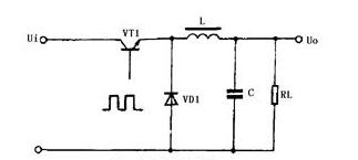
This circuit uses fewer components. Like the other two circuits introduced below, it only needs to use inductors, capacitors and diodes to implement.
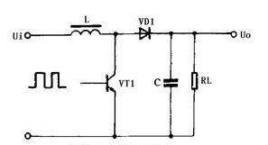
Boost switching power supply
The voltage stabilizing circuit of the boost switching power supply is shown in Figure 8. When the switch VT1 is turned on, the inductor L stores energy. When the switching tube VT1 is turned off, the inductor L induces left negative and right positive voltages. This voltage is superimposed on the input voltage and supplies power to the load through the diode VD1, so that the output voltage is greater than the input voltage, forming a boost switching power supply.
Reversible switching power supply
he typical circuit of the reversing switching power supply is shown in Figure 9. This circuit is also called a buck-boost switching power supply. Regardless of whether the pulsating DC voltage before the switch VT1 is higher or lower than the stable voltage at the output end, the circuit can work normally.
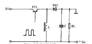
When the switch VT1 is turned on, the inductor L stores energy, the diode VD1 is turned off, and the load RL is powered by the last charge of the capacitor C. When the switch VT1 is turned off, the current in the inductor L continues to flow and induces an upper negative voltage and a lower positive voltage, which supplies power to the load through the diode VD1 and charges the capacitor C at the same time.
The above introduces the basic working principle and various circuit types of pulse width modulation switching regulated power supply. In practical applications, there will be a variety of actual control circuits, but no matter what, they are all developed on these basis of.
Read more: The Basic Principles of PCB Wiring Layout for SwitchingBest seller SMT Machine :Qihe smt line products
-
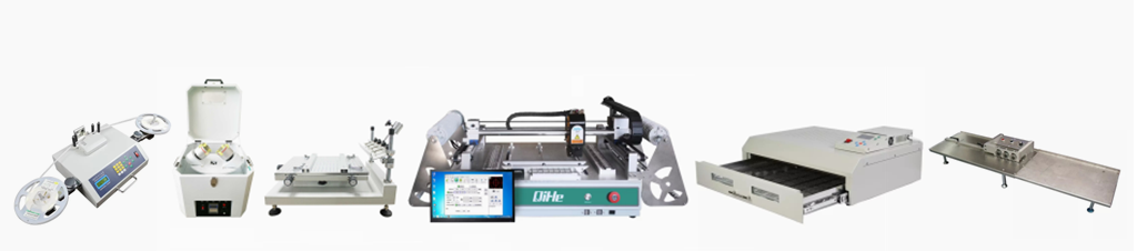
 SMT semi-automatic pick and place machine with Dispenser
 -
TVM925 SMT pick and place machine 4 head 38 feeders slots assembly of electronic components
-
Q10 SMT Automatic pick and place machine 10 Heads 100 Slots High Precision and High Efficiency SMT/LED Assembly
-
Q6 SMT pick and place machine 6heads 50slots With PCB Rail Servo Pick&Place Machine
-
Q4 SMT pick and place machine 4heads 50slots With PCB Rail Servo Pick&Place Machine
-
TVM802B Plus SMT pick and place machine 2heads 58slots desktop pick&place deluxe edition
-
QM10 SMT pick and place machine 10heads 80slots Fully Automatic Chip mounter SMT Assembly
-
TVM802BX SMT pick and place machine 2heads 46slots desktop pnp mounter deluxe edition
-
QL41 SMT pick and place machine 4heads 8slots LED for 1.2meters led strip pick&place machine


What is SMT in engineering?
Surface mount technology is a part of the electronic assembly that deals with the mounting of electronic components to the surface of a PCB. Electronic components mounted this way are called surface-mounted devices (SMD). SMT was developed to minimize manufacturing costs while making efficient use of board space.Qihe SMT company develops and produces all kinds of SMT equipment suitable for world wide market, including pnp machine,reflow oven,stencil printer,pcb handling machines,and other pick and place machine products.
Small desktop pick and place machine TVM802A,TVM802B,TVM802AX,TVM802BX series suitable for beginners, for hobbiest or low vol usag.
Advanced level 4-head LED strip placement QL41 led machines and with rail universal series Q4,TVM925S,TVM926S,pick and place
Fully automatic 6-10-head placement QM61,QM62,QM81,QM10,machines, which are suitable for high volume mass production in factories.
Know more about us https://www.qhsmt.com/about-qihe-smt-equipment/
Follow us on social media https://www.facebook.com/Qihesmt/
What is SMT in programming?
Offline Automated Programming vs Inline SMT Programming
Qihe pick and place machine can be programmed directly on the SMT equipment .
Or Coordinates can also be imported csv file through programming software.
Currently supported software such as protel,DXP,Altium Designer,Pads,Candes,proteus,DXP.
Inline SMT programming is a solution to consider for narrow segments of device programming requiring short programming times, with medium to high volume, for just one pick and place machine device type.
WHAT IS SMT pick and place machine?
SMT (Surface Mounted Technology) is a comprehensive system engineering technology, which covers substrates, design, equipment, components, assembly processes, production accessories and management. When it comes to SMT pick and place machines, the automatic SMT production line requires automatic loading and unloading machine, automatic solder paste printing machine, placement machine, reflow soldering machine, AOI inspection equipment, conveyor,connecting table, etc. For these SMT assembly line equipment, Qihe SMT can offer you machines in prototype SMT line, small SMT production line, mass production SMT line at low SMT line cost. Contact us now if you are interested.pick and place
WHAT IS SMT ASSEMBLY LINE?
With the development of technology, future electronic products will be lighter, smaller and thinner. Traditional assembly technology can no longer meet the requirements of high-precision and high-density assembly. A new type of PCB assembly technology-SMT (Surface Mount Technology) has emerged. SMT Assembly is the use of automated machines to assemble electronic components on the surface of the circuit board. Its density, high speed, standardization and other characteristics occupies an absolute advantage in the field of circuit assembly technology. In addition, pick and place machine SMT assembly has a wide range of uses.
https://www.qhsmt.com/fully-automatic-smt-pick-and-place-machine-line/