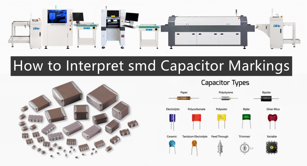
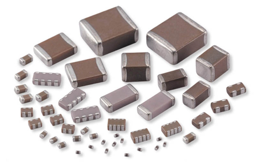
There are many types of capacitor labels compared to resistor labels. It’s difficult to see the markings on small capacitors because of their small body surface area. This article explains how to read the markings on almost all types of modern capacitors manufactured abroad. Your capacitors may be labeled in a different order than the one stated in this article. What’s more, some capacitors lack voltage and tolerance values—you only need a capacitance value to create a low-voltage circuit.Today qihe smt pick and place machine sharing how to Interpret Capacitor Markings
Understand capacitors and capacitor markings
The function and expression method of capacitor
It consists of two metal poles with an insulating medium sandwiched between them. The main characteristic of capacitors is to block DC and AC, so they are often used for interstage coupling, filtering, decoupling, bypassing and signal tuning. The capacitor is represented by “C” plus a number in the circuit, such as C8, which represents the capacitor numbered 8 in the circuit.
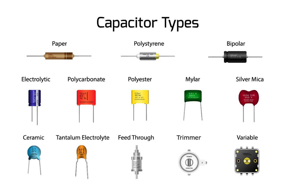
Classification of capacitors
Capacitors are divided according to different media: gas dielectric capacitors, liquid dielectric capacitors, inorganic solid dielectric capacitors, organic solid dielectric capacitors and electrolytic capacitors. According to polarity, they are divided into: polarized capacitors and non-polar capacitors. According to the structure, it can be divided into: fixed capacitor, variable capacitor and trimmer capacitor.
The capacity of the capacitor
Capacitance represents the amount of electrical energy that can be stored. The impeding effect of capacitance on AC signals is called capacitive reactance. Capacitive reactance is related to the frequency and capacitance of AC signals. Capacitive reactance XC=1/2πf c (f represents the frequency of AC signals and C represents capacitance).
The capacity unit and withstand voltage of the capacitor
The basic unit of capacitance is F (farad), and other units include: millifarad (mF), microfarad (uF), nanofarad (nF), and picofarad (pF). Since the capacity in unit F is too large, what we see are generally units of μF, nF, and pF. Conversion relationship: 1F=1000000μF, 1μF=1000nF=1000000pF.
Each capacitor has its withstand voltage value, represented by V. Generally, the nominal withstand voltage values of electrodeless capacitors are relatively high: 63V, 100V, 160V, 250V, 400V, 600V, 1000V, etc. The withstand voltage of polarized capacitors is relatively low. Generally, the nominal withstand voltage values are: 4V, 6.3V, 10V, 16V, 25V, 35V, 50V, 63V, 80V, 100V, 220V, 400V, etc.
Capacitor labeling method and capacity error
The labeling methods of capacitors are divided into: direct marking method, color marking method and numerical marking method. For capacitors with relatively large volumes, the direct scaling method is often used. If it is 0.005, it means 0.005uF=5nF. If it is 5n, it means 5nF.
Number scale method: Generally, three digits are used to indicate the capacity, the first two digits represent significant digits, and the third digit is the power of 10. For example: 102 means 10x10x10 PF=1000PF, 203 means 20x10x10x10 PF.
Color marking method uses different colors to represent different numbers along the direction of the capacitor lead. The first and second rings represent the capacitance, and the third color represents the number of zeros after the significant digit (unit is pF). The numerical values represented by the colors are: black=0, brown=1, red=2, orange=3, yellow=4, green=5, blue=6, purple=7, gray=8, white=9.
The capacitance error is represented by the symbols F, G, J, K, L, and M. The allowable errors are respectively ±1%, ±2%, ±5%, ±10%, ±15%, and ±20%.
Distinguish and measure the positive and negative poles of capacitance.
The black block with the mark on the capacitor is the negative terminal. There are two semicircles on the PCB at the position of the capacitor. The colored semicircle corresponds to the negative electrode. The length of the pins is also used to distinguish the positive and negative poles. Long pins are positive and short pins are negative.
When we don’t know the positive and negative poles of the capacitor, we can use a multimeter to measure it. The medium between the two poles of the capacitor is not an absolute insulator, and its resistance is not infinite, but a limited value, generally above 1000 megohms. The resistance between the two poles of the capacitor is called insulation resistance or leakage resistance.
Only when the positive terminal of the electrolytic capacitor is connected to the positive power supply (black test lead during electrical blocking) and the negative terminal is connected to the negative power supply (red test lead during electrical blocking), the leakage current of the electrolytic capacitor is small (the leakage resistance is large). On the contrary, the leakage current of the electrolytic capacitor increases (the leakage resistance decreases). In this way, we first assume that a certain pole is the “+” pole, and the multimeter selects the R100 or R1K block.
Then the assumed “+” pole is connected to the black test lead of the multimeter, and the other electrode is connected to the red test lead of the multimeter. Note down the scale at which the needle stops (the resistance value is higher if the needle is to the left). For a digital multimeter, the reading can be read directly. Then discharge the capacitor (touch the two leads), then reverse the two test leads and re-measure. In the two measurements, the time the needle last rested on the left (or had a large resistance), the black test lead was connected to the positive electrode of the electrolytic capacitor.
Some experiences and four misunderstandings about the use of capacitors
Some experience: When the polarity of the line cannot be determined in the circuit, it is recommended to use non-polar electrolytic capacitors. The ripple current through the electrolytic capacitor cannot exceed its allowable range. If the specified value is exceeded, capacitors that can withstand large ripple currents need to be selected. The operating voltage of the capacitor cannot exceed its rated voltage. When soldering capacitors, the soldering iron should keep a certain distance from the plastic shell of the capacitor to prevent the plastic sleeve from rupturing due to overheating. And the welding time should not exceed 10 seconds, and the welding temperature should not exceed 260 degrees Celsius.
Resistance
- Parameter identification: The unit of resistance is ohm (Ω), and the unit of magnification is: kiloohm (KΩ), megaohm (MΩ), etc. The conversion method is: 1 megaohm = 1,000 kiloohms = 1,000,000 ohms.
There are three methods for labeling parameters of resistors, namely direct marking method, color marking method and numerical marking method.
a. The numerical standard method is mainly used for small-volume circuits such as patches. For example: 472 means 47×100Ω (i.e. 4.7K); 104 means 100K.
b. The color ring marking method is the most commonly used. Common ones are four-color ring resistors and five-color ring resistors (precision resistors). The last digit represents the allowable deviation, the second to last digit represents the magnification, and the first 2 or 3 digits are significant figures.
The meaning of the color circle of the resistor is as shown in the following table:
Color silver gold black brown red orange yellow green blue purple gray white
Valid figures 0 1 2 3 4 5 6 7 8 9
Ratio 10^ -2 10^ -1 10^0 10^1 10^2 10^3 10^4 10^5 10^6 10^7 10^8 10^9
Allowable deviation ±10% ±5% ±1% ±2% ±0.5% ±0.2% ±0.1%
Best seller SMT Machine :Qihe smt line products
-
 SMT semi-automatic pick and place machine with Dispenser
 -
TVM925 SMT pick and place machine 4 head 38 feeders slots assembly of electronic components
-
Q10 SMT Automatic pick and place machine 10 Heads 100 Slots High Precision and High Efficiency SMT/LED Assembly
-
Q6 SMT pick and place machine 6heads 50slots With PCB Rail Servo Pick&Place Machine
-
Q4 SMT pick and place machine 4heads 50slots With PCB Rail Servo Pick&Place Machine
-
TVM802B Plus SMT pick and place machine 2heads 58slots desktop pick&place deluxe edition
-
QM10 SMT pick and place machine 10heads 80slots Fully Automatic Chip mounter SMT Assembly
-
TVM802BX SMT pick and place machine 2heads 46slots desktop pnp mounter deluxe edition
-
QL41 SMT pick and place machine 4heads 8slots LED for 1.2meters led strip pick&place machine


What is SMT in engineering?
Surface mount technology is a part of the electronic assembly that deals with the mounting of electronic components to the surface of a PCB. Electronic components mounted this way are called surface-mounted devices (SMD). SMT was developed to minimize manufacturing costs while making efficient use of board space.Qihe SMT company develops and produces all kinds of SMT equipment suitable for world wide market, including pnp machine,reflow oven,stencil printer,pcb handling machines,and other products.
Small desktop pick and place machine TVM802A,TVM802B,TVM802AX,TVM802BX series suitable for beginners, for hobbiest or low vol usag.
Advanced level 4-head LED strip placement QL41 led machines and with rail universal series Q4,TVM925S,TVM926S,pick and place
Fully automatic 6-10-head placement pick and place machine QM61,QM62,QM81,QM10,machines, which are suitable for high volume mass production in factories.
Know more about us https://www.qhsmt.com/about-qihe-smt-equipment/
Follow us on social media https://www.facebook.com/Qihesmt/
What is SMT in programming?
Offline Automated Programming vs Inline SMT Programming
Qihe pick and place machine can be programmed directly on the SMT equipment .
Or Coordinates can also be imported csv file through programming software.
Currently supported software such as protel,DXP,Altium Designer,Pads,Candes,proteus,DXP.
Inline SMT programming is a solution to consider for narrow segments of device programming requiring short programming times, with medium to high volume, for just one device type pick and place machine.
WHAT IS SMT pick and place machine?
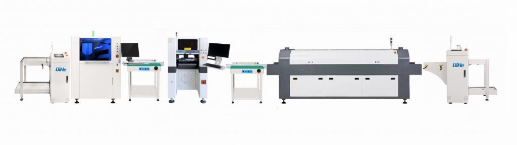
SMT (Surface Mounted Technology) is a comprehensive system engineering technology, which covers substrates, design, equipment, components, assembly processes, production accessories and management. When it comes to SMT pick and place machines, the automatic SMT production line requires automatic loading and unloading machine, automatic solder paste printing machine, placement machine, reflow soldering machine, AOI inspection equipment, conveyor,connecting table, etc. For these SMT assembly line equipment, Qihe SMT can offer you machines in prototype SMT line, small SMT production line, mass production SMT line at low SMT line cost. Contact us now if you are interested.pick and place
WHAT IS SMT ASSEMBLY LINE?
With the development of technology, future electronic products will be lighter, smaller and thinner. Traditional assembly technology can no longer meet the requirements of high-precision and high-density assembly. A new type of PCB assembly technology-SMT (Surface Mount Technology) has emerged. SMT Assembly is the use of automated machines to assemble electronic components on the surface of the circuit board. Its density, high speed, standardization and other characteristics occupies an absolute advantage in the field of circuit assembly technology. In addition, SMT assembly has a wide range of uses.
https://www.qhsmt.com/fully-automatic-smt-pick-and-place-machine-line/