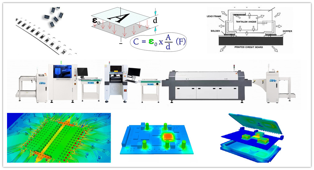
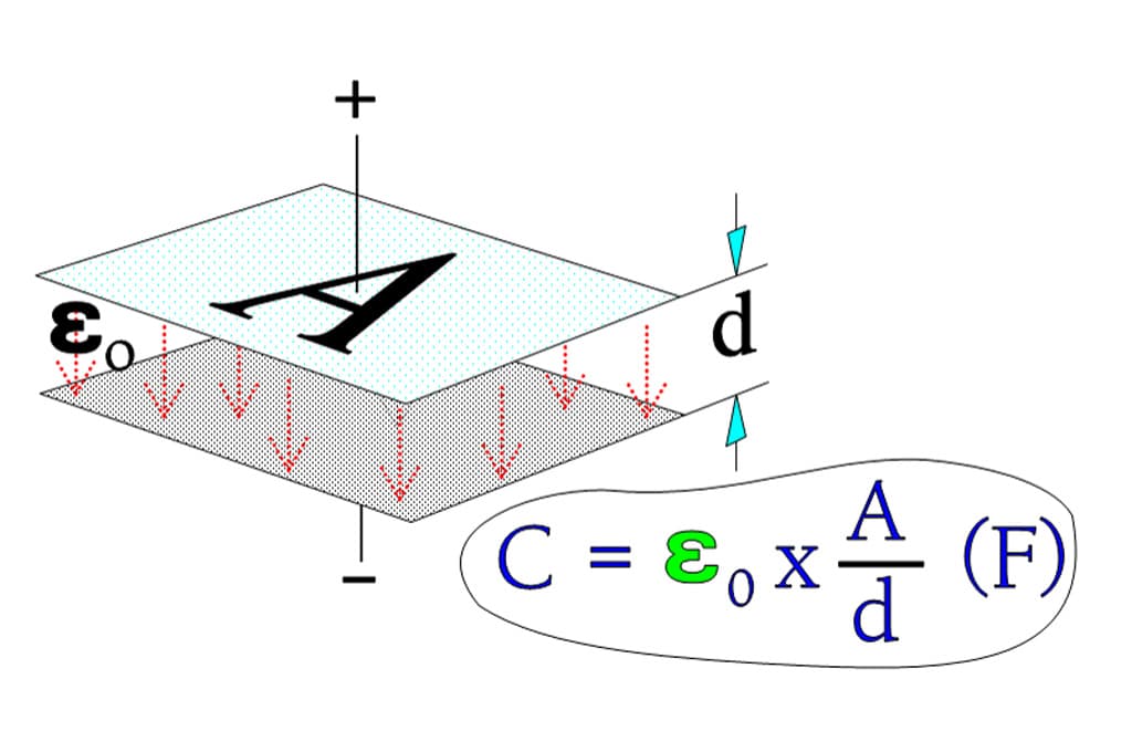
The capacitance of a capacitor is affected by the area of the plates, the distance between the plates, and the ability of the dielectric to support electrostatic forces. This post qihe smt pick and place machine explores how varying these parameters affects the capacitance of a capacitor.
Therefore, the higher the values of capacitance, input frequency and load resistance, the lower the value of ripple factor. Hence, to reduce the ripples in a rectifier circuit with capacitor filter should be increased, Input frequency should be increased, and Capacitor with high capacitance should be used.Smt pick and place
When evaluating ripple, it is usually done around the two components of ripple voltage and ripple current. In most applications, ripple is a circuit condition that engineers want to minimize. For example, in an AC-DC converter that converts AC power into a stable DC output, efforts must be made to avoid a phenomenon in which the AC power is superimposed on the DC output with a small, frequency-dependent change signal. However, in other cases, ripple can be a necessary design feature, for example, a clock signal or digital signal can use changes in voltage levels to switch the state of a device.
In the latter case, ripple considerations are fairly simple: don’t let the peak voltage exceed the rated voltage of the capacitor. However, it is important to remember that the peak voltage is the sum of the highest ripple voltage and the DC bias voltage in the circuit. In addition, for electrolytic capacitors using tantalum, aluminum and niobium oxide technology, there is another point that requires special attention: do not let the minimum value of the ripple voltage drop below zero potential, because this will cause the capacitor to work in reverse. bias condition. This requirement also applies to Class II ceramic capacitors for low frequency applications.Smt pick and place
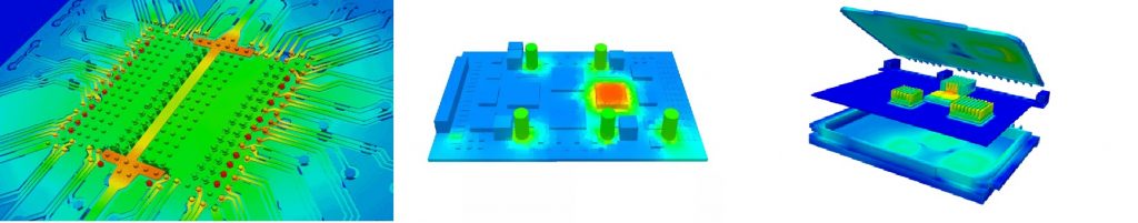
Capacitors act as a charge reservoir; when the voltage increases, they are charged; when the voltage decreases, they discharge into the load; they essentially smooth the signal. The capacitor will experience varying voltages and, depending on the applied power, possibly varying currents, as well as continuous and intermittent pulsating power. Regardless of the form of the input, the changes experienced by the capacitive electric field will cause the dipoles in the dielectric material to oscillate, thereby generating heat. This reaction behavior, known as self-heating, is one of the main reasons why dielectric properties are important because any parasitic resistance (ESR) or inductance (ESL) will increase energy consumption.
A dielectric with low losses (i.e., low ESR/DF and low ESL) will heat less than a dielectric with high ESR and DF; however, these parameters also vary with frequency, as different dielectric materials provide optimal performance at different frequency ranges ( i.e., minimal fever).
The capacitor dielectric is very thin and may only account for a small portion of the capacitor’s total mass, so other materials used in its construction also need to be considered when evaluating ripple. For example, in non-polar capacitors (such as ceramic or film capacitors), the capacitor plate is metallic; in polar capacitors (such as tantalum or aluminum), there is a metal anode (in niobium oxide technology, the anode is a conductive oxide) and a semiconductor cathode (such as manganese dioxide or conducting polymer). On the external connections or pins, there are various conductive contacts, including metals (such as copper, nickel, silver, palladium and tin, etc.) and conductive epoxy. When AC signals or current pass through these materials, they will have Some degree of fever.
To understand how these factors come into play, consider the example of using solid tantalum capacitors to smooth residual AC ripple current in the output stage of a DC power supply. First, since this is a polar technology, a positive voltage bias is required to prevent the AC component from causing a reverse bias condition. This bias voltage is usually the rated output voltage of the power supply.
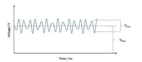
The ripple voltage is superimposed on the bias voltage
Before we consider ripple, we must note the heating generated by the applied DC bias. Capacitors are not ideal devices. A parasitic phenomenon is the parallel resistance across the dielectric material. This resistance will cause leakage current (DCL) to occur. This small DC current will cause heating, but unlike the ripple conditions of other typical applications, this heating is usually negligible. A 100uF/10V chip tantalum capacitor has a DCL of no more than 10uA (100uA@85℃) at room temperature, so its maximum power consumption is 1mW.
Next, we look at the power dissipated by the ripple value of the current (equal to I2R, where “I” is the root mean square [rms] of the current) at a given frequency (equal to “R”, the ESR of the capacitor at the same frequency) .
We start by examining a sinusoidal ripple current and its RMS equivalent. If at a certain frequency, we make a 1A Irms current flow through a 100mΩESR capacitor, the resulting power consumption is 100mW. If power is supplied continuously, this current will cause the capacitor to heat internally until it reaches a level of contact with the surrounding environment based on the thermal capacity of the capacitor element structure and packaging material, as well as all measures taken to dissipate heat to the surroundings (e.g., a combination of convection, conduction, and radiation). balance. In this case, the ripple heating is 100 times greater than the DC leakage heating, so the latter (as mentioned earlier) can be ignored. However, when evaluating a new capacitor, checking for DC leakage and heating is always the first option.Smt pick and place
Having defined several factors that determine the self-heating caused by applied ripple, we can now proceed to set a limit. Although, there is almost no fixed answer to the question “How much ripple is too big?” like there is to the question “How long is the rope?”; so the standard approach is to just set an arbitrary temperature change and Use this as a reference point and work backwards to work out how much ripple would be needed to cause this change for a given capacitance.
Typically, depending on the capacitor technology, it is recommended to select +10°C or +20°C as the maximum temperature increment tolerance. Calculate the ripple required to produce the above conditions using the following reference conditions:
1) 25℃ ambient temperature;
2) The ripple is a continuous sine wave, and its frequency corresponds to the ESR test frequency of the capacitor;
3) Capacitors in “free space” (i.e., without heat sinks or forced cooling, and free to radiate heat in at least five directions (another direction may be soldered to a test board));
4) Also, in the case of polarized capacitors, a DC bias is applied to ensure that the associated ripple voltage does not create any reverse voltage across the capacitor.
Then, increase the ripple current and monitor the device temperature until it reaches equilibrium at its recommended temperature tolerance point, T, above the ambient temperature.
The measured Irms is often quoted as a limit for ripple current, but it is not an actual limit in the sense of a maximum voltage calibration or a maximum ESR limit; rather, it is a best practice condition that can be used as a basis for application evaluation.
This measurement also allows calculation of the capacitor’s power dissipation and thermal resistance. Power consumption “P” is given by:
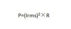
Among them: “R” is the ESR of the capacitor at the ripple frequency, and the thermal impedance is the heat generated per unit time and temperature, in °C/W.
From the above, we can see that for a given capacitor, power dissipation is a function of frequency (due to the influence of ESR). Thermal impedance (in this case, measured empirically) can also be calculated based on the mass of the capacitor and the thermal capacity of its constituent materials. However, the environmental conditions of the capacitor (i.e., the thermal management of the system) also have an impact on the heating of the capacitor in the application.
Capacitors with the same volume and materials have the same thermal resistance. Therefore, if the ESR is known, the power dissipation per unit time can be calculated for each nominal parameter capacitor in the same product family. The expected temperature rise can also be calculated by multiplying the thermal resistance by the power dissipation.
Returning to the ripple current measurement, this value will immediately indicate whether the selected nominal value can be used for a given application. To be able to fine-tune this value to match actual ripple conditions, manufacturers provide typical ESR vs. frequency and ESR vs. temperature data so that the ESR can be matched to the application conditions. This information is usually given in the data sheet under the Nominal Values entry, and is also available through software that allows the user to vary frequency and temperature. If the ripple is non-sinusoidal, discontinuous, or intermittent (e.g., pulse discharge), the designer will need to employ an appropriate transformation method to calculate the rms equivalent or use the peak value as the worst-case scenario.Smt pick and place
The system can then be thermally modeled, taking into account any forced cooling or heat dissipation measures that would lower the capacitor’s temperature; it should also be noted that other heat-generating devices near the capacitor may increase its temperature. .
In the absence of sufficient data for either cooling method, empirical methods can be used, which are often the most accurate. This can be achieved by operating the circuit under worst-case conditions and measuring the temperature rise of the device above the ambient temperature with the help of a thermocouple or pyrometer.
The first thing to confirm is that the equilibrium temperature does not exceed the maximum operating temperature of the capacitor, and that the associated peak ripple voltage (plus any applied bias voltage) does not exceed the maximum operating voltage. For many capacitor technologies, ESR decreases as temperature increases, so the impact of ESR on ripple heating is reduced. However, it is either accounted for in the vendor’s data sheet or is not required (if the device is actually measured in the application).
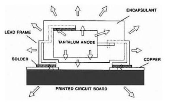
Heat dissipation model of chip tantalum capacitors
Lead frame
Solder
tantalum anode
printed circuit board
encapsulant
copper
If the device operates within the allowable range of all operating parameters, there will be no problem; for critical applications, the actual reliability of the capacitor can always be recalculated based on its actual maximum temperature, rather than the ambient temperature of the circuit. If the calculated or measured temperature rise is above the recommended operating range, the device may still be capable of operation (if the above conditions are met), but the supplier should still be contacted to confirm whether other considerations need to be made in this case. pressure.Smt pick and place
After determining what factors affect heating, let’s look at some practical applications.
For low voltage (such as 1.8V~5.5V power rail) DC applications, high-capacitance chip multilayer ceramic capacitors (MLCC) and solid tantalum electrolytic capacitors are the first choice for DC power supply filter capacitors in the range of 10kHz to 10MHz. . These technologies enable capacitance values of hundreds of microfarads (uF) at low voltage levels in a small form factor. The temperature characteristics of X5R chip multilayer ceramic capacitors allow it to achieve particularly high capacitance values. Its typical ESR is in the range of 1~10 mΩ, but it has an upper temperature limit of 85°C. Although the capacitance of X5R devices is maximized for low voltage levels, a characteristic of these capacitors is that their capacitance decreases with applied voltage (voltage coefficient). At the same time, their capacitance also decreases with increasing operating temperature. Small (temperature coefficient).
However, its ESR remains low, so ripple current capability will not be affected. In applications where low body capacitance losses are preferred, the X7R temperature characteristics can be used. For a given size and voltage rating, the nominal capacitance value of the In the ℃ range, the temperature coefficient will also be more stringent.
Solid tantalum electrolytic capacitors are polar devices that require DC bias in ripple applications. They can provide extremely high capacitance values in the range of 100μf~1mF; and their typical ESR is an order of magnitude higher than that of MLCCs. Therefore, replacing tantalum capacitors with niobium oxide capacitors is a solution worth considering. Tantalum solid electrolytic capacitors use tantalum metal as the base anode material (i.e., the positive side capacitor plate), coated with tantalum pentoxide dielectric, and use manganese dioxide or polymer film as the negative electrode material (i.e., the negative side capacitor plate).
Niobium oxide capacitors have a conductive NbO anode and a niobium pentoxide dielectric. Niobium is a member of the same family of tantalum, but has a lower density. They are processed similarly and have similar electrical properties; however, the niobium dielectric is more robust for any given voltage rating. This means that for the same voltage level, niobium operates with smaller electric field stress than tantalum and is more reliable, but it also limits its maximum rated voltage and slightly increases its ESR. But in corrugated applications, the small difference in ESR is compensated by the higher specific heat and lower thermal impedance of the niobium material. This means that tantalum and niobium oxides of similar specifications have similar ripple performance.
At low ripple frequencies, the typical ESR of an X5R or X7R (Class II dielectric) MLCC increases faster than that of tantalum or niobium. Therefore, the latter is preferred for audio applications, but neither should be used in low-frequency applications (e.g., line applications below 100Hz) due to excessive self-heating. When selecting larger stacked ceramic capacitors for switch mode applications, the manufacturer’s software will often issue an alert at low frequencies, when self-heating or the ripple voltage itself exceeds limits, and may also result in the use of Class II ceramics where no DC voltage is applied Bias and get another warning.
The dielectric structure of a Class II ceramic capacitor can be thought of as a collection of domains with internal dipoles that change in response to changes in applied AC voltage. However, without DC bias for compensation, the domains will flip when experiencing reverse voltage, increasing internal heating. Therefore, for low frequency applications, a lower dielectric constant (i.e., a lower capacitance value for a given size and voltage/capacitance value combination), larger size, or a stacking of multiple capacitive elements (e.g., stacked ceramic capacitors in switched mode), so Class I dielectrics such as NP0/C0G are generally a better choice.Smt pick and place
For large film capacitors in the range of 500uF~1mF/450V~1kV used in DC link applications (vehicle inverters for electric vehicles are typical applications), the ripple current will cause the device to heat up, but its large mass This means that its thermal time constant needs to be considered. In fact, in some cases, in ripple applications, it can take an hour or so for the capacitor to reach equilibrium temperature. Polypropylene is often the dielectric of choice due to its extremely low power dissipation and resulting low heat generation under high ripple current conditions. This capacitor often has custom specifications for specific vehicle and/or inverter applications.
For example, all film capacitors have an inherent self-healing mechanism, but this self-healing mechanism can be enhanced by using special structures within the metal electrode system so that the total capacitive surface area can be divided into multiple parallel micro-elements to prevent short circuits Fault. Prolonged periods of high temperature and applied voltage will degrade capacitance values over time, but if the application’s busy/idle times are known, the deviation of the actual capacitance value from the nominal value can be accurately calculated and accounted for in the initial design.
Read more: In-depth understanding of capacitance, ripple and self-heatingBest seller SMT Machine :Qihe smt line products
-
 SMT semi-automatic pick and place machine with Dispenser
 -
TVM925 SMT pick and place machine 4 head 38 feeders slots assembly of electronic components
-
Q10 SMT Automatic pick and place machine 10 Heads 100 Slots High Precision and High Efficiency SMT/LED Assembly
-
Q6 SMT pick and place machine 6heads 50slots With PCB Rail Servo Pick&Place Machine
-
Q4 SMT pick and place machine 4heads 50slots With PCB Rail Servo Pick&Place Machine
-
TVM802B Plus SMT pick and place machine 2heads 58slots desktop pick&place deluxe edition
-
QM10 SMT pick and place machine 10heads 80slots Fully Automatic Chip mounter SMT Assembly
-
TVM802BX SMT pick and place machine 2heads 46slots desktop pnp mounter deluxe edition
-
QL41 SMT pick and place machine 4heads 8slots LED for 1.2meters led strip pick&place machine


What is SMT in engineering?
Surface mount technology is a part of the electronic assembly that deals with the mounting of electronic components to the surface of a PCB. Electronic components mounted this way are called surface-mounted devices (SMD). SMT was developed to minimize manufacturing costs while making efficient use of board space.Qihe SMT company develops and produces all kinds of SMT equipment suitable for world wide market, including pnp machine,reflow oven,stencil printer,pcb handling machines,and other Smt pick and placeproducts.
Small desktop pick and place machine TVM802A,TVM802B,TVM802AX,TVM802BX series suitable for beginners, for hobbiest or low vol usag.
Advanced level 4-head LED strip placement QL41 led machines and with rail universal series Q4,TVM925S,TVM926S,Smt pick and place
Fully automatic 6-10-head placement QM61,QM62,QM81,QM10,machines, which are suitable for high volume mass production in factories.
Know more about us https://www.qhsmt.com/about-qihe-smt-equipment/
Follow us on social media https://www.facebook.com/Qihesmt/
What is SMT in programming?
Offline Automated Programming vs Inline SMT Programming
Qihe pick and place machine can be programmed directly on the SMT equipment .
Or Coordinates can also be imported csv file through programming software.
Currently supported software such as protel,DXP,Altium Designer,Pads,Candes,proteus,DXP.
Inline SMT programming is a solution to consider for narrow segments of device programming requiring short programming times, with medium to high volume, for just one device type.
WHAT IS SMT pick and place machine?
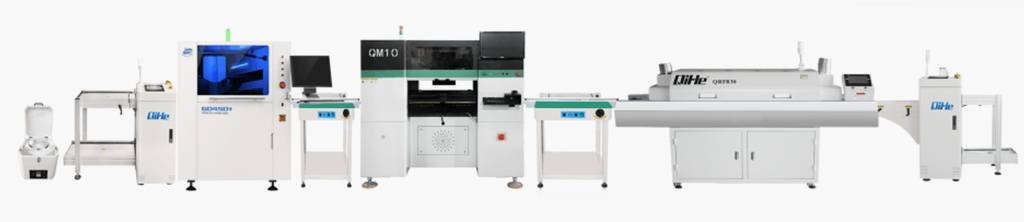
SMT (Surface Mounted Technology) is a comprehensive system engineering technology, which covers substrates, design, equipment, components, assembly processes, production accessories and management. When it comes to SMT pick and place machines, the automatic SMT production line requires automatic loading and unloading machine, automatic solder paste printing machine, placement machine, reflow soldering machine, AOI inspection equipment, conveyor,connecting table, etc. For these SMT assembly line equipment, Qihe SMT can offer you machines in prototype SMT line, small SMT production line, mass production SMT line at low SMT line cost. Contact us now if you are interested.Smt pick and place
WHAT IS SMT ASSEMBLY LINE?
With the development of technology, future electronic products will be lighter, smaller and thinner. Traditional assembly technology can no longer meet the requirements of high-precision and high-density assembly. A new type of PCB assembly technology-SMT (Surface Mount Technology) has emerged. Smt pick and place Assembly is the use of automated machines to assemble electronic components on the surface of the circuit board. Its density, high speed, standardization and other characteristics occupies an absolute advantage in the field of circuit assembly technology. In addition, SMT assembly has a wide range of uses.
https://www.qhsmt.com/fully-automatic-smt-pick-and-place-machine-line/