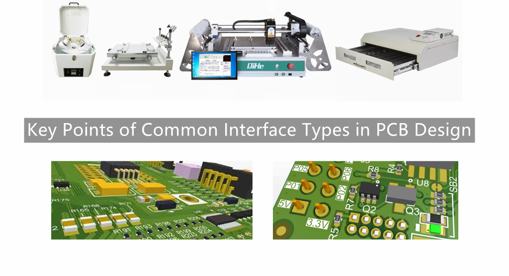
We know that there may be some problems in the data exchange between the various sub-modules of the circuit system that cause the signal to fail to “flow” normally and with high quality. The respective signal types are inconsistent (such as sensor detection of light signals), etc. At this time, we should consider using the corresponding interface to deal with this problem well.Today qihe smt pick and place machine sharing some key points of common interface types in PCB design.
The key points of commonly used interface types in circuit design are explained below.
TTL level interface
This type of interface is basically a cliché. From studying analog circuits and digital circuits in college, for general circuit design, TTL level interface is basically inseparable from the “relationship”! Its speed is generally limited to within 30MHz. This is due to the presence of several pF input capacitors at the input of the BJT (forming an LPF). If the input signal exceeds a certain frequency, the signal will be “lost”. Its driving capacity is generally a maximum of tens of milliamperes. The normal working signal voltage is generally higher, if it is close to the ECL circuit with lower signal voltage, there will be more obvious crosstalk problems.
CMOS level interface
We are not unfamiliar with it, and we have often dealt with it. Some semiconductor characteristics about CMOS do not need to be long-winded here. Many people know that under normal circumstances, the power consumption and anti-interference ability of CMOS are much better than that of TTL. but! What is little known is that CMOS series actually consumes more power than TTL at high switching frequencies. As for why this is the case, please ask the semiconductor physics theory. Since the operating voltage of CMOS can be very small at present, and some FPGA core operating voltages are even close to 1.5V, this makes the noise margin between levels much smaller than that of TTL, thus aggravating the noise caused by voltage fluctuations. Signal judgment error. As we all know, the input impedance of a CMOS circuit is very high, so its coupling capacitance can be very small, and there is no need to use a large electrolytic capacitor. Since CMOS circuits usually have weak drive capability, TTL conversion must be performed before driving ECL circuits. In addition, when designing CMOS interface circuits, care should be taken to avoid excessive capacitive loads, otherwise the rise time will be slower, and the power consumption of the driving device will also increase (because capacitive loads do not consume power)
ECL level interface
This is an old friend inside the computer system! Because its speed “runs” fast enough, it can even run to hundreds of MHz! This is because the BJT inside the ECL is not in a saturated state when it is turned on, so that the turn-on and turn-off time of the BJT can be reduced, and the working speed can naturally be increased. But, there is a price to pay! Its fatal injury: high power consumption! The EMI problem it causes is worth considering, and the anti-interference ability is not much better. If anyone can compromise these two factors, then he (she) should make a fortune. It should also be noted that the general ECL integrated circuit needs a negative power supply, that is to say, its output voltage is negative, and a special level shift circuit is required at this time.
RS-232 level interface
basically no one who plays electronic technology does not know it (unless he or she is just a “layman” in electronic technology). It is a low-speed serial communication interface standard. It should be noted that its level standard is a bit “abnormal”: the high level is -12V, and the low level is +12V. So, when we try to communicate with peripherals through the computer, a level conversion chip MAX232 is naturally indispensable. But we have to be soberly aware of some of its shortcomings, such as relatively slow data transmission speed and short transmission distance.
Differential balanced level interface
It uses the relative output voltage (uA-uB) of a pair of terminals A and B to represent the signal. Generally, this differential signal will pass through a complex noise environment during signal transmission, resulting in Basically the same amount of noise is generated on both lines, and the energy of the noise will be canceled out at the receiving end, so it can achieve longer distance and higher rate transmission. The commonly used RS-485 interface in the industry adopts the differential transmission mode, which has a good ability to resist common mode interference.
Optical isolation interface
Optical coupling uses optical signals as the medium to realize the coupling and transmission of electrical signals. Its “benefit” is that it can achieve electrical isolation, so it has excellent anti-interference ability. Under the condition of high operating frequency of the circuit, basically only the high-speed photoelectric isolation interface circuit can meet the needs of data transmission. Sometimes in order to realize the control of high voltage and high current, we must design and use the optical isolation interface circuit to connect these low-level, small current TTL or CMOS circuits as mentioned above, because the input circuit and output circuit of the optical isolation interface The room can withstand a high voltage of several thousand volts, which is enough for general applications. In addition, the input part and output part of the optical isolation interface must use independent power supplies, otherwise there is still an electrical connection, so it is not called isolation.
Coil coupling interface
It has good electrical isolation characteristics, but the allowed signal bandwidth is limited. For example, transformer coupling, its power transmission efficiency is very high, and the output power is basically close to its input power. Therefore, for a step-up transformer, it can have a higher output voltage, but it can only give a lower current. In addition, the high-frequency and low-frequency characteristics of the transformer are not optimistic, but its biggest feature is that it can realize impedance transformation. When matched properly, the load can obtain enough power. Therefore, the transformer coupling interface is important in the design of power amplifier circuits. Very “popular”.
Read more: Key Points of Common Interface Types in PCB DesignBest seller SMT Machine :Qihe smt line products
-
 SMT semi-automatic pick and place machine with Dispenser
 -
TVM925 SMT pick and place machine 4 head 38 feeders slots assembly of electronic components
-
Q10 SMT Automatic pick and place machine 10 Heads 100 Slots High Precision and High Efficiency SMT/LED Assembly
-
Q6 SMT pick and place machine 6heads 50slots With PCB Rail Servo Pick&Place Machine
-
Q4 SMT pick and place machine 4heads 50slots With PCB Rail Servo Pick&Place Machine
-
TVM802B Plus SMT pick and place machine 2heads 58slots desktop pick&place deluxe edition
-
QM10 SMT pick and place machine 10heads 80slots Fully Automatic Chip mounter SMT Assembly
-
TVM802BX SMT pick and place machine 2heads 46slots desktop pnp mounter deluxe edition
-
QL41 SMT pick and place machine 4heads 8slots LED for 1.2meters led strip pick&place machine


What is SMT in engineering?
Surface mount technology is a part of the electronic assembly that deals with the mounting of electronic components to the surface of a PCB. Electronic components mounted this way are called surface-mounted devices (SMD). SMT was developed to minimize manufacturing costs while making efficient use of board space.Qihe SMT company develops and produces all kinds of SMT equipment suitable for world wide market, including pnp machine,reflow oven,stencil printer,pcb handling machines,and other products.
Small desktop pick and place machine TVM802A,TVM802B,TVM802AX,TVM802BX series suitable for beginners, for hobbiest or low vol usag.
Advanced level 4-head LED strip placement QL41 led machines and with rail universal series TVM925S,TVM926S,
Fully automatic 6-10-head placement QM61,QM62,QM81,QM10,machines, which are suitable for high volume mass production in factories.
Know more about us https://www.qhsmt.com/about-qihe-smt-equipment/
Follow us on social media https://www.facebook.com/Qihesmt/
What is SMT in programming?
Offline Automated Programming vs Inline SMT Programming
Qihe pick and place machine can be programmed directly on the SMT equipment .
Or Coordinates can also be imported csv file through programming software.
Currently supported software such as protel,DXP,Altium Designer,Pads,Candes,proteus,DXP.
Inline SMT programming is a solution to consider for narrow segments of device programming requiring short programming times, with medium to high volume, for just one device type.
WHAT IS SMT pick and place machine?
SMT (Surface Mounted Technology) is a comprehensive system engineering technology, which covers substrates, design, equipment, components, assembly processes, production accessories and management. When it comes to SMT pick and place machines, the automatic SMT production line requires automatic loading and unloading machine, automatic solder paste printing machine, placement machine, reflow soldering machine, AOI inspection equipment, conveyor,connecting table, etc. For these SMT assembly line equipment, Qihe SMT can offer you machines in prototype SMT line, small SMT production line, mass production SMT line at low SMT line cost. Contact us now if you are interested.
WHAT IS SMT ASSEMBLY LINE?
With the development of technology, future electronic products will be lighter, smaller and thinner. Traditional assembly technology can no longer meet the requirements of high-precision and high-density assembly. A new type of PCB assembly technology-SMT (Surface Mount Technology) has emerged. SMT Assembly is the use of automated machines to assemble electronic components on the surface of the circuit board. Its density, high speed, standardization and other characteristics occupies an absolute advantage in the field of circuit assembly technology. In addition, SMT assembly has a wide range of uses.
https://www.qhsmt.com/fully-automatic-smt-pick-and-place-machine-line/